Saia-Burgess Controls AG
Manual Manual PCD 1 / PCD 2 Series │ Document 26 / 737 EN22 │ 2013-11-26
5
Input/output (I/O) modules
5-88
Analogue output modules with electrically isolation
In the FBs the output values are not limited to 0 … 1023, so the whole range of the
module can be used.
For voltages > 10 V or currents > 20 mA, values >1023 may be output, and for
voltages < 0 V or
< -10 V, negative values may be output. (With the W615 it is not possible to output
negative currents).
This extended range does depend on the tolerances of the components, and cannot
be guaranteed.
Connection concept for voltage and current outputs
The voltage and current output signals are connected directly to the 14-pole terminal
block (A0 … A5 / A3 and -).
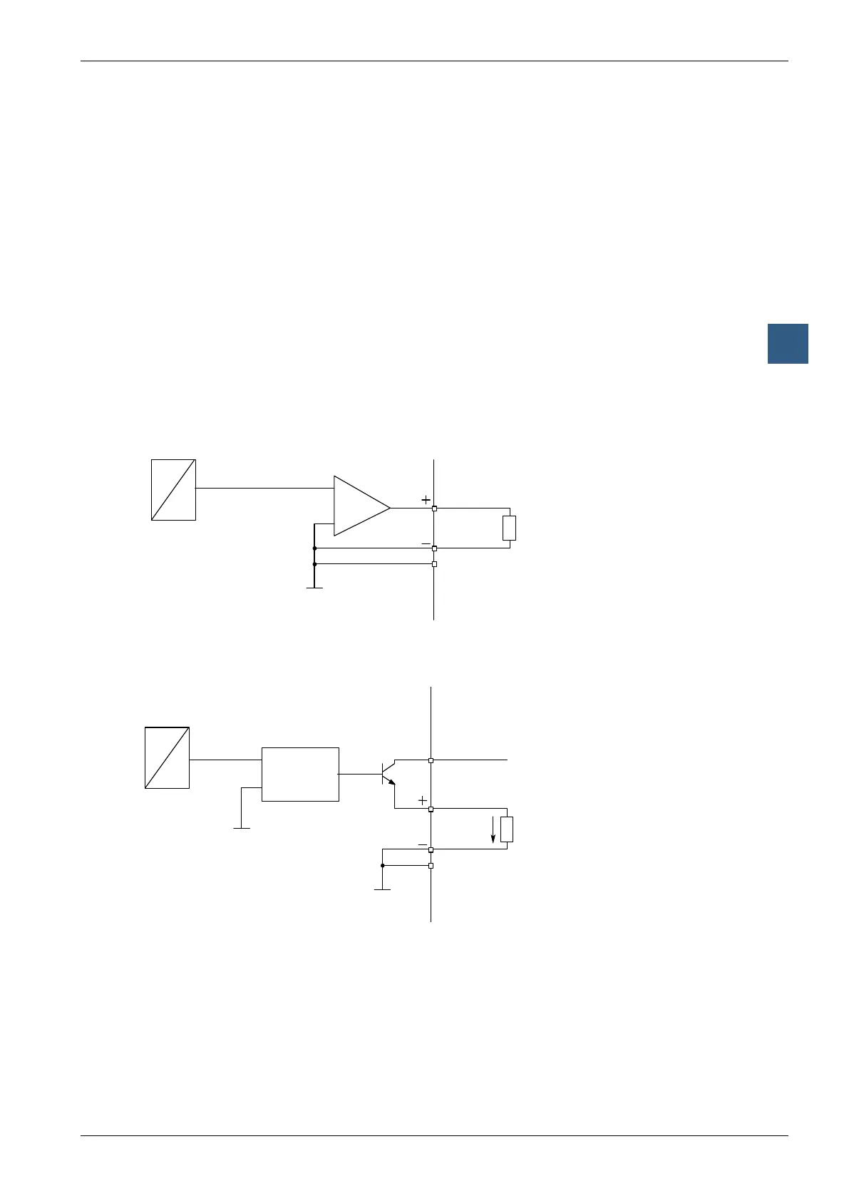
The following connection diagram shows a typical wiring layout for:
● voltage outputs with the PCD2.W605 and .W625 modules or
● current outputs for the PCD2.W615 module
Connection for 0 … 10 V (W605) or -10 V … +10 V (W625):
D
A
5
U
13
4
(A2)
For voltage outputs no external supply is needed.
Connection for 0 … 20 mA (W615)
4 (A2)
D
A
5
I
VOLTAGE
CONTROLLED
CURRENT
SOURCE
13
12
An external 24 VDC supply is required for current outputs.
 Loading...


