Saia-Burgess Controls AG
Manual Manual PCD 1 / PCD 2 Series │ Document 26 / 737 EN22 │ 2013-11-26
5
Input/output (I/O) modules
5-92
Analogue input and output modules
Internal current consumption:
(from V+ bus)
0 mA
External current consumption: 0 mA
Terminals: Pluggable 10-pole screw terminal block
(4 405 4847 0), for wires up to 1.5 mm²
As the current consumption of this module is considerable, when using a number
of them in the same system, the total load for all modules must be taken into
consideration..
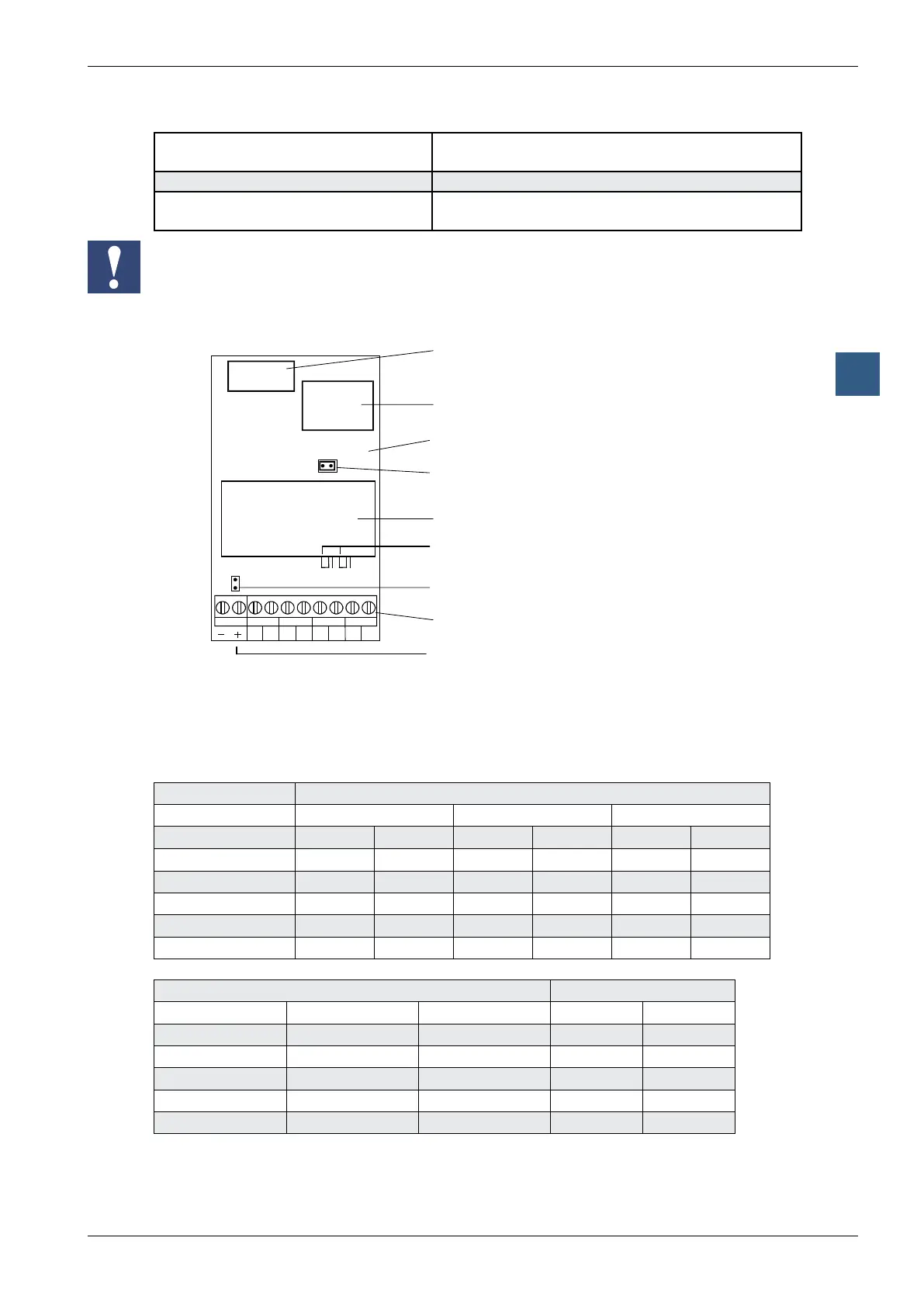
Terminals
Bus connector
DC-DC converter
Basic module
Jumper: inputs unipolar (U)
Substitution module
Jumper U/B 0 and U/B 1
on substitution module
Jumper: inputs bipolar (B)
Screw terminals
+ must not be connected
The negative terminals “–” of outputs are connected internally to the ground, each via
a 100 Ω resistor.
Analogue/digital values
Inputs
Input signals Digital values
Classic xx7 Simatic
unipolar bipolar unipolar bipolar unipolar bipolar
+10 V 4095 4095 4095 4095 27648 27648
+5 V 2047 3071 2047 3071 13824 13824
0 V 0 2047 0 2047 0 0
-5 V 0 1023 0 1023 0 -13824
-10 V 0 0 0 0 0 -27648
Outputs
Digital values Output signals
Classic xx7 Simatic unipolar bipolar
4095 4095 27648 +10.0 V +10.0 V
3071 3071 20736 +7.5 V + 5.0 V
2047 2047 13824 +5.0 V 0 V
1023 1023 6912 +2.5 V -5.0 V
0 0 0 0 V -10.0 V