Saia-Burgess Controls AG
Manual Manual PCD 1 / PCD 2 Series │ Document 26 / 737 EN22 │ 2013-11-26
5
Input/output (I/O) modules
5-93
Analogue input and output modules
PCD2.W500 Module, fully equipped
(with additional module plugged on)
Apart from the bus connector, DC-DC converter and terminals, the base module
carries the two input channels with the 2-pole jumper for unipolar or bipolar operation
and a number of preset potentiometers, which cannot be adjusted by the user.
The plug-on module contains the two analogue outputs with the two 3-pole jumpers
for the individual unipolar or bipolar operation of each output.
The module also works without the plug-on module.
Changing the jumpers
On this circuit board there are components that are sensitive to electrostatic
discharges. For further information, refer to Appendix B, “Icons”.
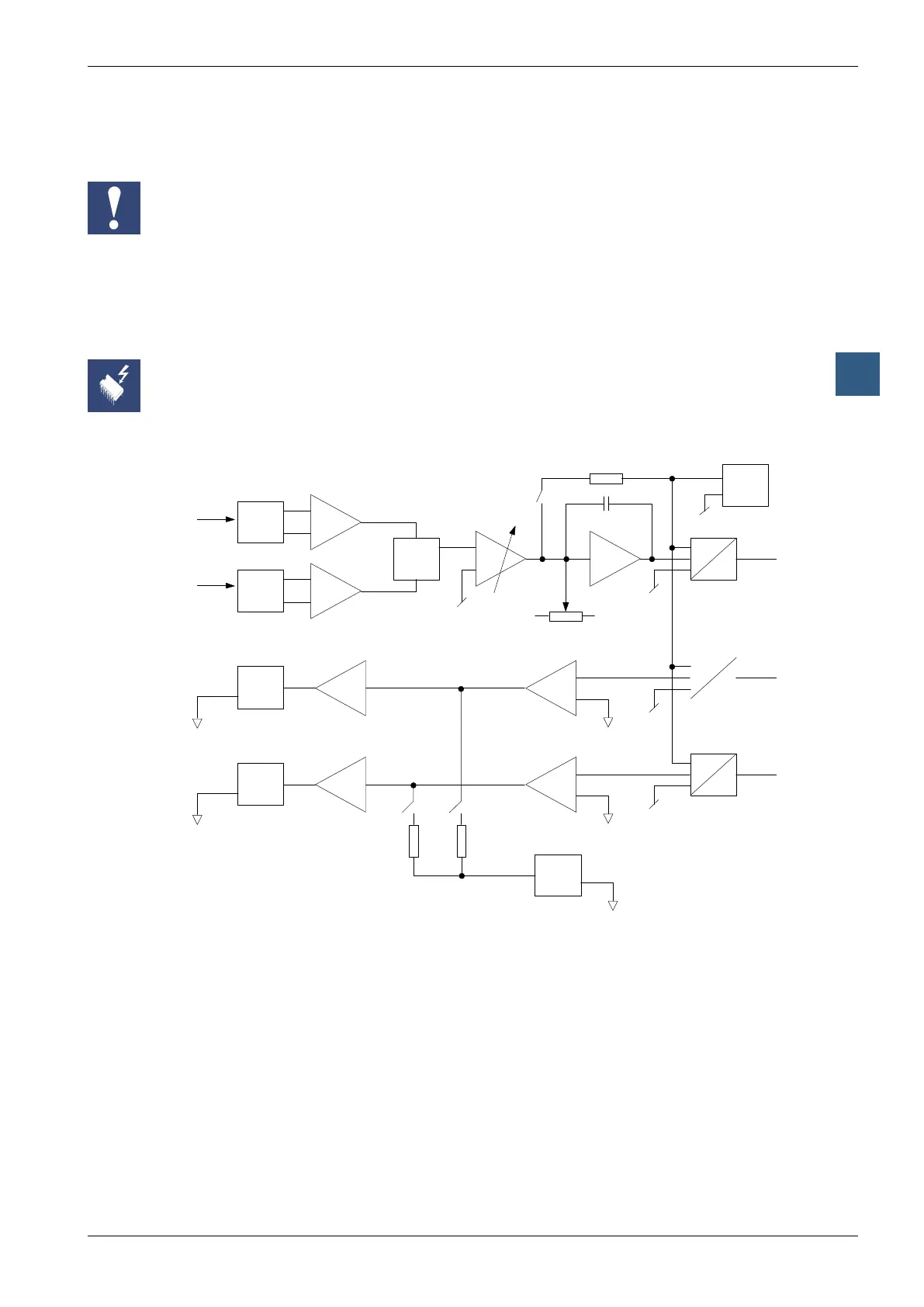
Block diagram
Prot.
EMC
Diff.
Mux.
Prot.
EMC
Diff.
Input 0
Input 1
/4
/8
V Adj.
A
D
Bus
Ref.
2.5 V
+/- 10 V
A
D
Bus
Diff.
x2
Prot.
EMC
x2
x4
A
D
Bus
Diff.
x2
Prot.
EMC
x2
x4
Output 0
Output 1
Ref.
2.5 V
+/- 10 V
Programming
Reset
When the module or CPU powers up, both analogue outputs of the PCD2.W500
Module are set at the maximum value of +10 V (or a random value between 0 and
+10 V). If this should cause problems, XOB 16 (the cold-start routine) should be used
to initialize both these outputs to zero or any desired cold-start value.