Saia-Burgess Controls AG
Manual Manual PCD 1 / PCD 2 Series │ Document 26 / 737 EN22 │ 2013-11-26
5
Input/output (I/O) modules
5-128
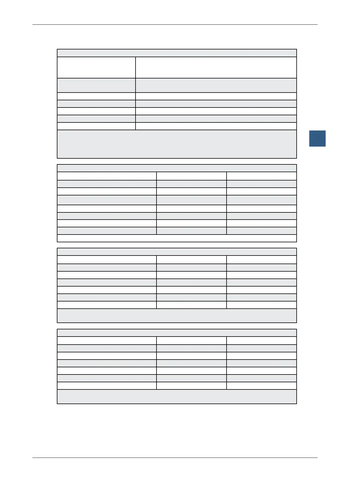
Motion control modules for servo-motors
Digital inputs for all PCD2.H32x modules per axis
Number of inputs 1 reference input “REF”
1)
2 limit switch inputs “LS1 / LS2”
1)
1 synchronization input “SI”
2)
Input voltage 24 VDC (6 to 32 VDC) smoothed,
max. residual ripple 10 %
“Low” range -30 … +5 V
“High” range +15 … +32 V
Input current at 24 VDC 7 mA (typically)
Circuit type electrically connected
Reaction time 300 µs
1)
For safety reasons, normally-closed (NC) or PNP sensors should be used for the
reference and limit switches. For this reason, these inputs work in sink mode
(negative logic, i.e. LED = on when 0 V at input).
2)
The synchronization input works in source mode (positive logic)
Digital outputs for all PCD2.H32x modules
Axis 1 Axis 2
Outputs SO SO
Supply Uext Uext
U
ext
(typically 24 VDC) 6 … 32 VDC 6 … 32 VDC
I out 5 … 500 mA 5 … 500 mA
Voltage drop at 500 mA < 0.3 V < 0.3 V
Short circuit protection Yes
1)
Yes
1)
Electrical isolation No No
1)
The short circuit current is restricted to max. 1.6 A
Analogue outputs for modules PCD2.H320 and PCD2.H325
Axis 1 Axis 2
Outputs OUT OUT
Resolution (incl. sign bit) 12 bit 12 bit
Short circuit protection Yes Yes
Electrical isolation No No
Output voltage uctuation
1)
+/- 10 V +/- 10 V
Minimum load impedance 3 kΩ 3 kΩ
1)
Setting accuracy ± 5 mV. Balancing output voltage is carried out in the factory, and
the value is stored in a digitally programmable potentiometer
Analogue outputs for modules PCD2.H322 and PCD2.H327
Axis 1 Axis 2
Outputs OUT NC
Resolution (incl. sign bit) 12 bit -
Short circuit protection Yes -
Electrical isolation No -
Output voltage uctuation
1)
+/- 10 V -
Minimum load impedance 3 kΩ -
1)
Setting accuracy ± 5 mV. Balancing output voltage is carried out in the factory, and
the value is stored in a digitally programmable potentiometer