Saia-Burgess Controls AG
Manual Manual PCD 1 / PCD 2 Series │ Document 26 / 737 EN22 │ 2013-11-26
5
Input/output (I/O) modules
5-130
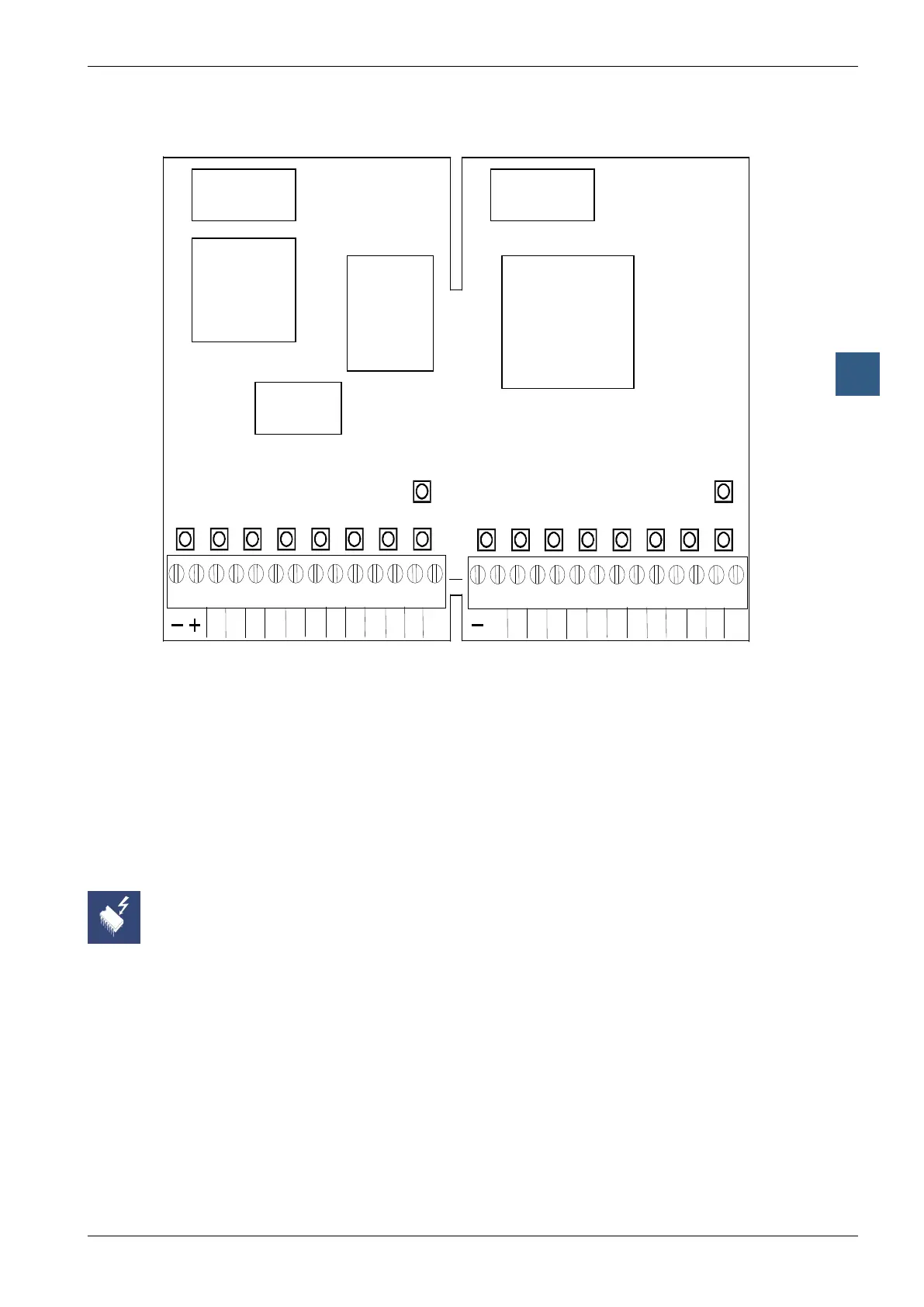
Motion control modules for servo-motors
LEDs and connection terminals
5
/I
I
/
/A A
S
REF
S
/I
IN /
B /A A
S
LS1 REF
S
Screw terminal block J4, Axis 2
Screw terminal block J5, Axis 1
Trace
Memory
Bus
connector
Bus
connector
Addressing
circuit (FPGA)
Servo Processor
(DSP)
Peripheral
ASIC
LEDs LEDs
2xLED “IN” State of index input
2x LED “A” State of encoder input “A”
2xLED “B” State of encoder input “B”
2x LED “LS2” State of limit switch 2
2x LED “Ref” State of reference switch
2x LED “LS1” State of limit switch 1
2x LED “SO” State of synchronization output
2x LED “SI” State of synchronization input
1x LED “PWR” State of internal voltage (+/- 15 V)
1x LED “OK” State of controller
On this circuit board there are components that are sensitive to electrostatic
discharges. For further information, refer to Appendix B, “Icons”.