Wiring – differential Hall only
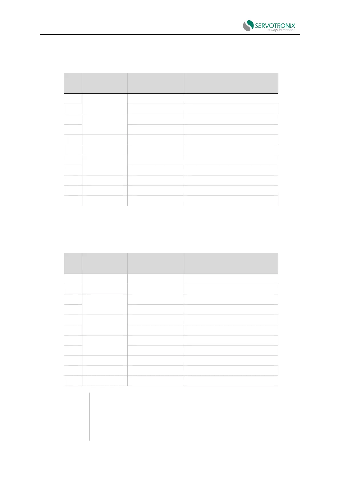
Table 4-23 Feedback wiring – differential Hall only
Incremental encoder A+/Hall U+
Incremental encoder A-/Hall U-
Incremental encoder B+/Hall V+
Incremental encoder B-/Hall V-
Incremental encoder Z+/Hall W+
Incremental encoder Z-/Hall W-
Wiring – Tamagawa incremental encoder
Table 4-24 Feedback wiring – Tamagawa incremental encoder
Incremental encoder A+/Hall U+
Incremental encoder A-/Hall U-
Incremental encoder B+/Hall V+
Incremental encoder B-/Hall V-
Incremental encoder Z+/Hall W+
Incremental encoder Z-/Hall W-
If the motor does not support a temperature sensor, do not connect pins 12 and
25.
Incremental encoder with Hall sensor and index pulse.
The signals A, B and Z use the same wiring as the Hall sensors U, V and W.
When powered on, the feedback will send Hall readings briefly, and then
continuously send A, B and Z signals.
Each time power is applied, PHASEFIND must be performed