Chapter 10 Operating Instructions
CLV 480 Bar Code Scanner
10-26 © SICK AG · Division Auto Ident · Germany · All rights reserved 8 010 080/O824/10-02-2005
Appendix
10.4 Optional heating
10.4.1 Features
• Integrated heater (permanently installed)
• Wider range of applications for CLV: up to max. –35 °C (–31 °F)
• Supply voltage 24 V DC +20 %/–10 %
• CLV enabled via internal temperature switch (power-up delay approx. 35 to 40 min. at
24 V DC and min. ambient temperature of –35
°C (–31 °F)
• Required cable cross-section (power supply): min. 0.75 mm
2
(approx. 20 AWG )
10.4.2 Design
The heating system comprises two parts:
• the front window heater
• the housing heater
The optional heating system is installed and tested at the factory. The user cannot install it
on site.
10.4.3 Function
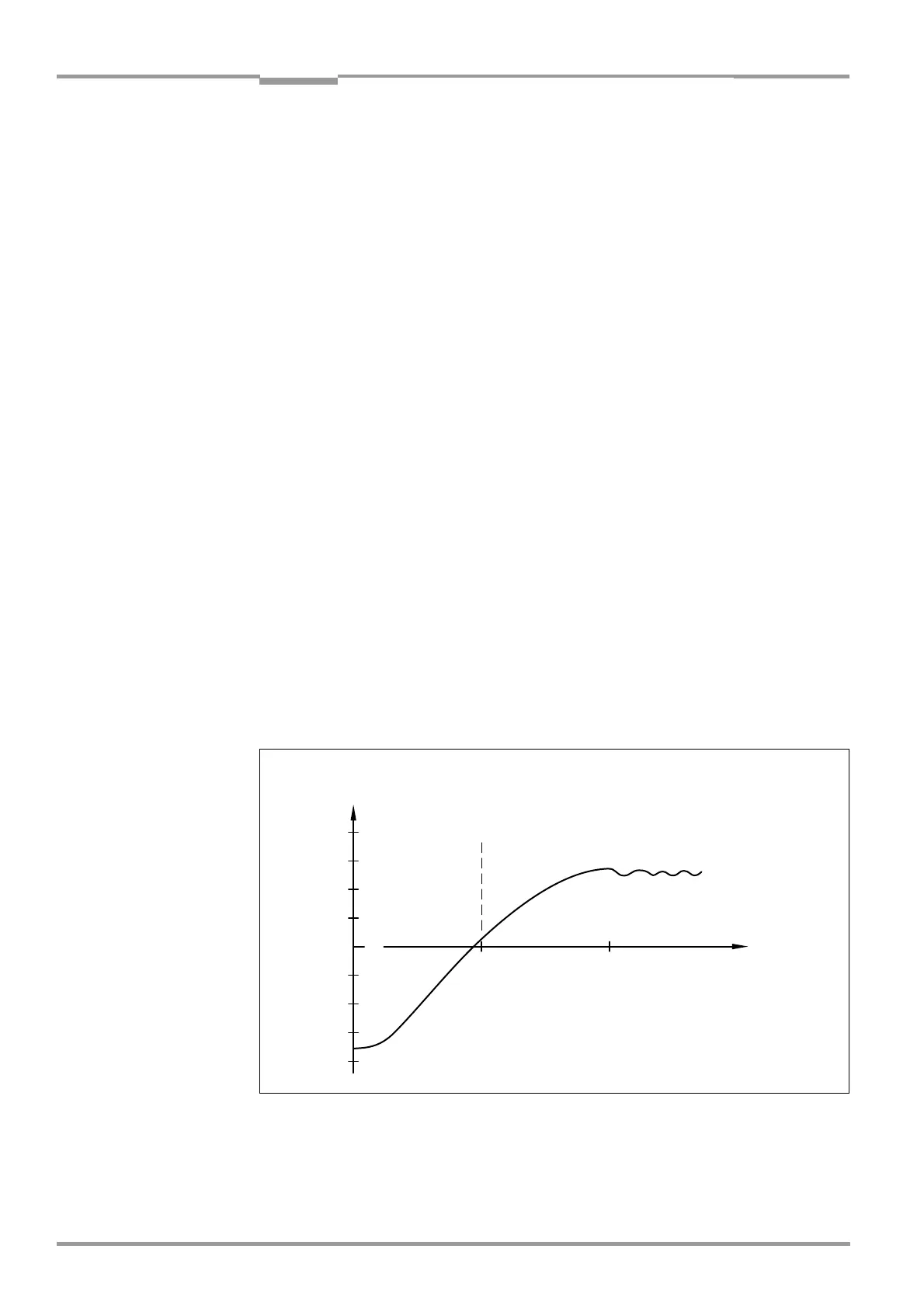
When the 24 V DC supply voltage is applied, a temperature switch first supplies electric
current to the heater only. This switch enables the supply voltage for the CLV when the in-
ternal temperature rises above +7 °C (+44.6 °F) during the warm-up phase (approx. 35
min). The device then performs a self-test and switches to Reading mode. The "Device Rea
-
dy" LED lights up to indicate that the device is ready.
When the internal temperature has reached approx. +25 °C (+77 °F), a further temperature
switch deactivates the housing heater and reactivates it if necessary. Reading mode is not
interrupted as a result. The front window heater remains active constantly. The temperature
curve inside the housing is shown in
Fig. 10-25.
Fig. 10-25: CLV with heater: temperature curve inside the housing
+40
+30
+20
+10
0
-10
-20
-30
-40
104
86
68
50
32
14
-4
-22
-40
40 80
Temperature
inside housing
The temperature enables the operating
voltage for the CLV internally
Time [min]
[°C]
[°F]