Operating Instructions Chapter 4
CLV 480 Bar Code Scanner
8 010 080/O824/10-02-2005 © SICK AG · Division Auto Ident · Germany · All rights reserved 4-3
Installation
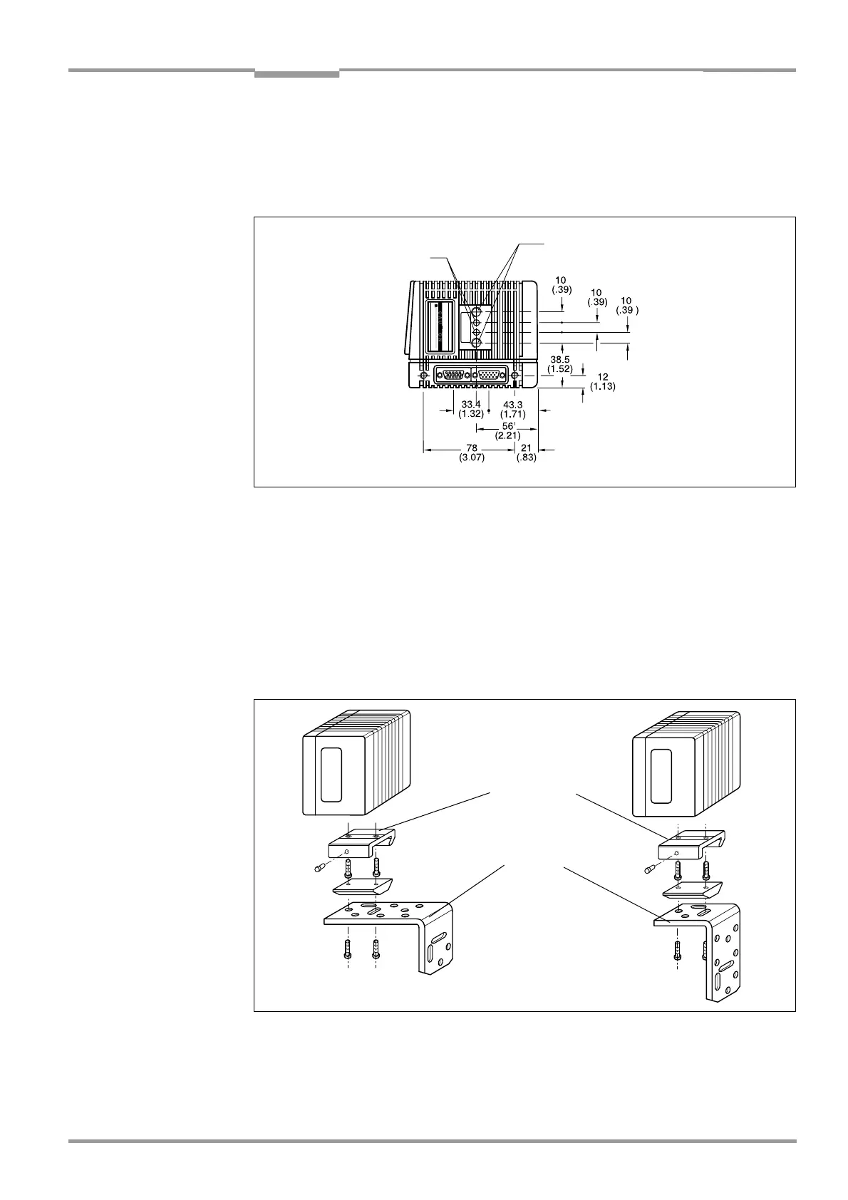
4.2.6 Mounting accessories
The CLV is secured in position using the two tapped blind holes (M6) above the electrial con-
nections. Fig. 4-2 shows the location of the threads near the line scanner.
The dimensions of the CLV housing are shown in Fig. 9-1 to Fig. 9-2, Page 9-4.
The CLV can be mounted using the SICK bracket:
• Mounting bracket, single no. 2 013 824
• Articulated bracket (2 x mounting bracket, single) no. 2 018 435
• Quick-clamping device no. 2 016 110
The brackets are designed to support a variety of mounting positions and alignments in two
planes.
Fig. 4-3 shows two mounting examples.
The elongated holes in the mounting bracket no. 2 013 824 and in the articulated bracket
no. 2 018 435 allow the CLV to be adjusted with a freedom of rotation of
±15°.
The dimensions of the mounting brackets are shown in Chapter 10.13 Dimensioned draw-
ings of the accessories, Page 10-57
Fig. 4-2: Line scanner: position of the securing threads on the CLV
Drilled hole, ∅ 3.6 mm,
6 mm (0.24 in) deep
Blind hole thread, M6,
7 mm (0.28 in) deep
Fig. 4-3: Line scanner: Mounting possibilities of the CLV
Quick-clamping
device
Mounting
bracket