Chapter 5 Operating Instructions
CLV 480 Bar Code Scanner
5-10 © SICK AG · Division Auto Ident · Germany · All rights reserved 8 010 080/O824/10-02-2005
Electrical installation
Tip
The device number can be selected on the DEVICE CONFIGURATION tab in the "CLV-Setup"
program.
5.4.3 Non-SICK Power supply unit/connections without the Connection Module
Power output
If an non-Sick Power supply unit is used instead of the AMS 60, it must be capable of
providing the following voltage and power values:
• For CLV without heater: 18 to 30 V DC, min. 20 W continuous power output
• For CLV with heater: 24 V DC +20 %/–10 %, min. 100 W
The non-Sick Power supply unit must provide the functional extra-low voltage in accordance
with IEC 364-4-41.
The output circuit must be reliably electrically isolated from the input circuit. To do so,
use a safety isolating transformer pursuant to IEC
742.
Wire cross-section
The wire cross-section for the power supply (Pin 1/Pin 5) should be at least 0.15 mm
2
(approx. 26 AWG), or 0.75 mm
2
(approx. 20 AWG) for CLVs with heater, with a max. length
of 10 m (32.8 ft).
a) Connecting the CLV without a connector cover/external parameter memory
The two cables no. 2 020 303 and no. 2 020 264 with open cable end on one side are
required to connect the CLV. The wire color assignments are shown in
Table 5-10 and
Table 5-11, Page 5-11. The cables must not be extended for CLVs with heater.
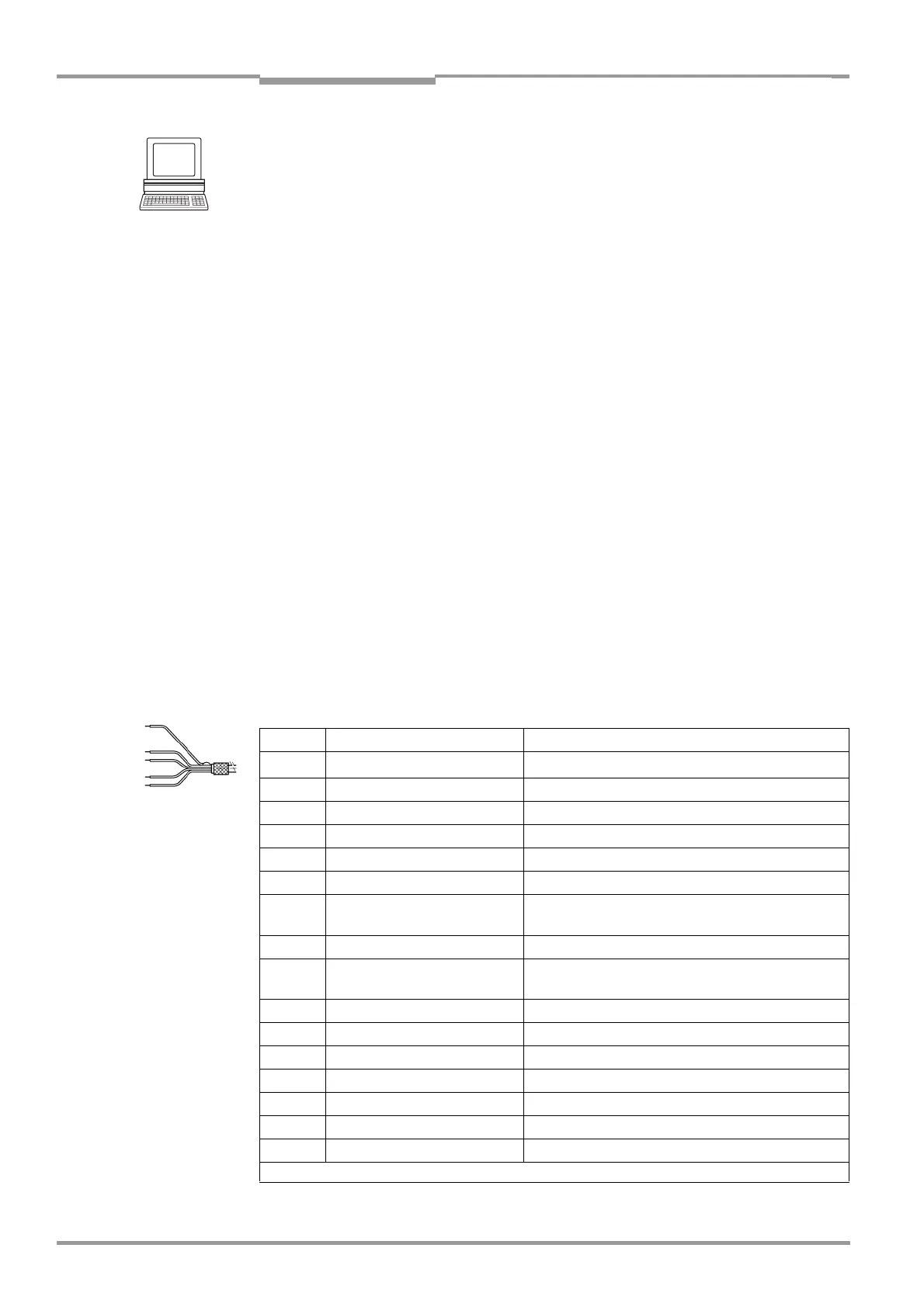
Connection cable no. 2 020 203 ("Host/Term" connection)
15-pin D Sub HD socket and open cable end
Pin Signal Wire color
1
1)
V
S
Red
2 RxD (RS 232), Terminal White
3 TxD (RS 232), Terminal Brown
4 Term (RS 422/485) Violet
5 GND Blue
6 RD+ (RS 422/485), Host Green
7 RD– (RS 422/485), Host
RxD (RS 232), Host
Yellow
8 TD+ (RS 422/485), Host Grey
9 TD– (RS 422/485), Host
TxD (RS 232), Host
Black
10 CAN H Grey-pink
11 n. c. Red-blue
12 CAN2 H White-green
13 CAN2 L Brown-green
14 n. c. White-yellow
15 CAN L Yellow-brown
– Shield Orange
1) Pin 1 is jumpered with Pin 1 of the "I/O" connection in the CLV
Table 5-10: Wire color assignment of the cable no. 2 020 303