Operating Instructions Chapter 10
CLV 480 Bar Code Scanner
8 010 080/O824/10-02-2005 © SICK AG · Division Auto Ident · Germany · All rights reserved 10-55
Appendix
b) CLV with heater
Temperature range of connection material:
Stationary: –50 to +70 °C (–58 to +158 °F); moving: –40 to +70 °C (–40 to +158 °F)
Note Other cable lengths/types for CLVs with heater available on request.
10.12.5 Plug-in connections
10.12.6 Reading pulse generators
The SICK catalog "SENSICK Sensors for Automation" (no. 8 006 530, English edition) con-
tains a large selection of photoelectric switches and photoelectric proximity switches as well
as the associated accessories (brackets, connection cables).
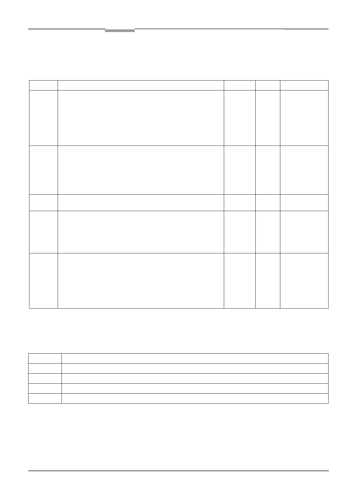
Order No. Description Wires Length Connection
2 021 689 Connector cover ("Scanner") with parameter memory (EEPROM) to
connector cover ("Host"), enclosure rating IP 65, with 2 connection
cables, each ∅ 8
mm (dia. 0.32 in), shielded. Each cover with 15-pin D
Sub HD socket and 15-pin D Sub HD plug.
Pin assignment of each cable identical to device connection, however pin
10 to pin 15 (CAN interfaces 1 and 2) not connected, pin 13 and pin 14
of "I/O" connection not connected.
Required: 1 per CLV
each 18 x
0.14 mm
2
(26 AWG)
3 m
(9.84 ft)
CLV 480 to
AMV 100/200
2 021 298 Connector cover ("Scanner") to connector cover ("Host"), enclosure rat-
ing IP 65, with 2 connection cables, each ∅ 6.7 mm (0.26 in), shielded.
Each cover with 15-pin D Sub HD socket and 15-pin D Sub HD plug.
Pin assignment of each cable identical to device connection, however pin
10 to pin 15 (CAN interfaces 1 and 2) of "Host/Term" connection not
connected; pin 13 and pin 14 of "I/O" connection not connected.
Required: 1 per CLV
each 18 x
0.14 mm
2
(26 AWG) +
2 x
1.5
mm
2
(16 AWG)
3 m
(9.84 ft)
CLV 480 to
AMV 100/200
2 021 299 As for 2 021 298, however longer cables As for
2 021 298
10 m
(32.8 ft)
As for 2 021 298
2 021 267 Connector cover, enclosure rating IP 65, with 2 connection cables, each
∅ 6.7 mm (0.26 in), shielded, two open ends (stripped).
Pin assignment of each cable identical to device connection, however pin
10 to pin 15 (CAN interfaces 1 and 2) of "Host/Term" connection not
connected; pin 13 and pin 14 of "I/O" connection not connected
Required: 1 per CLV
18 x
0.14 mm
2
(26 AWG) +
2 x 1.5 mm
2
(16 AWG)
3 m
(9.84 ft)
CLV 480 to
Host, sensors,
PLC and non-Sick
Power pack
2 027 543 Connector cover ("Scanner") with parameter memory (EEPROM) to
connector cover ("AMV/BMV"), enclosure rating IP 65, with 2 connection
cables, each ∅ 8 mm (dia. 0.32 in), shielded. Each cover with 15-pin D
Sub HD socket and 15-pin D Sub HD plug.
Pin assignment of each cable identical to device connection, however pin
11 to pin 14 (CAN interface 2) of "Host/Term" connection not con-
nected, pin 13 and pin 14 of "I/O" connection not connected.
Required: 1 per CLV
10 x 2 x
0.14 mm
2
(26 AWG) +
2 x 1.5 mm
2
(16 AWG)
3 m
(9.84 ft)
CLV 480 to
Host, sensors,
PLC and non-Sick
Power pack
Table 10-15: Accessories: cables and connector covers for the CLV with heater
Order No. Description
6 009 438 D Sub connector housing (metal) for 9-pin or 15-pin HD inserts
6 007 335 D Sub connector insert, 9-pin socket connector
6 010 019 D Sub connector insert, 15-pin HD socket connector
6 010 020 D Sub connector insert, 15-pin HD pin connector
Table 10-16: Accessories: plug-in connections