Chapter 5 Operating Instructions
CLV 480 Bar Code Scanner
5-16 © SICK AG · Division Auto Ident · Germany · All rights reserved 8 010 080/O824/10-02-2005
Electrical installation
For connecting the host interface via the AMV/S 60 Connection Module, see the Operating
Instructions "AMV/S 60 Connection Module" (no. 8 008 296).
Terminating the RS 422 interface
The interface can be terminated in the Connection Module. See the Operating Instructions
"AMV/S 60", "AMV 30.071", "AMV 100/200", or "BMS 20 Connection Modules".
Activating the RS 232 interface:
The RS 232 interface can be activated with the "CLV-Setup" program:
1. Choose the HOST INTERFACE tab.
2. Choose the RS 232 option from the HARDWARE drop-down list under DATA FORMAT.
3. Download the data to the CLV by clicking in the toolbar.
The DOWNLOAD PARAMETERS dialog box is displayed.
4. Confirm the dialog box by choosing PERMANENT.
The CLV uses the RS 232 version of the host interface.
Tip The communication parameters can be changed, if necessary, on the HOST INTERFACE tab.
To do so, change the values under DATA FORMAT and INTERFACE PROTOCOL.
5.5.5 Connecting the CAN interface
Instructions for the connection of CAN-interface 1 and for configuration of the CLV to use
the device in the SICK-specific CAN Scanner Network or in a CANopen network see the
Operating Instructions “Application of the CAN interface“ (no. 8 009 180, English edition).
5.5.6 Connecting the PC
The CLV is operated and configured with the PC-based "CLV-Setup" program. In order to do
so, you must connect the device to the PC via the terminal interface (auxiliary interface). Un
-
like the host interface, the terminal interface has a permanent data format and a fixed data
transfer rate.
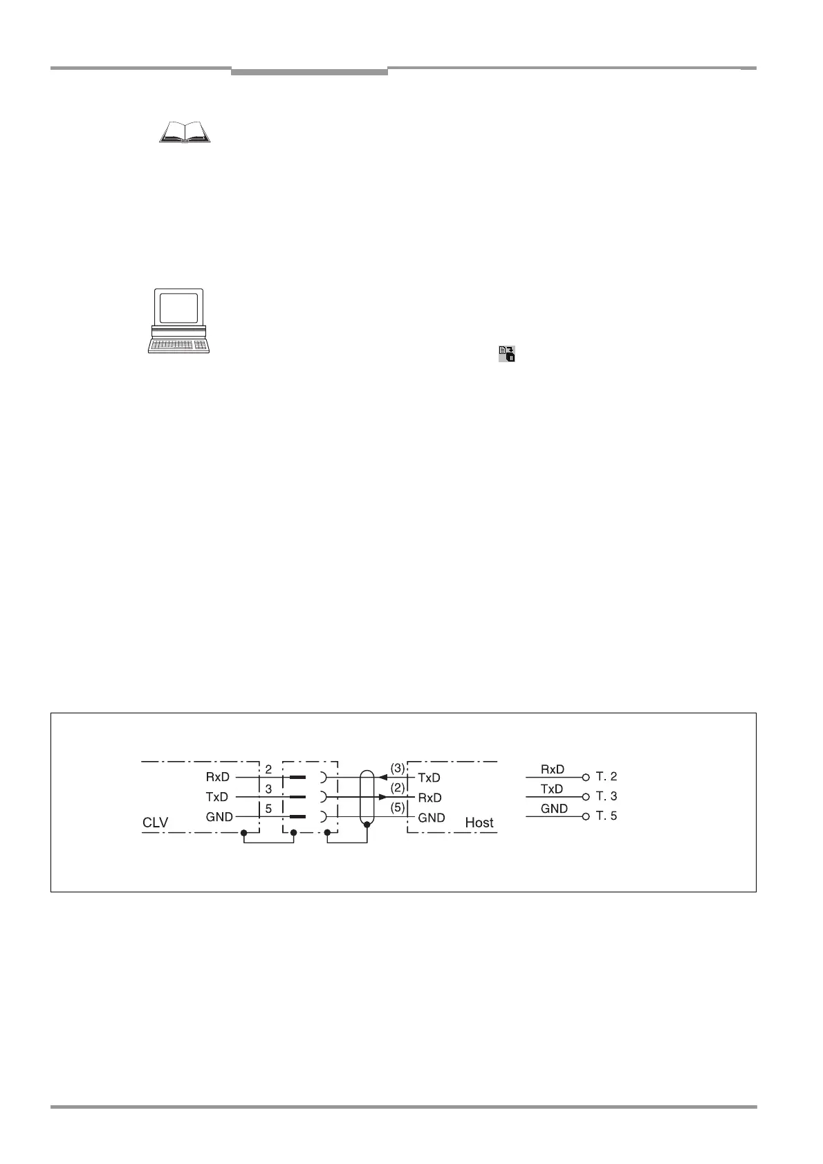
Fig. 5-3 shows how the terminal interface is connected. The cable length
should not be more than 10 m (32.8 ft).
1. Switch off the PC and power supply to the SICK Connection Module.
2. Connect the PC to the internal, 9-pin "Service" plug on the Connection Module.
To do so, use a 3-core RS 232 data cable (null modem cable), e. g. no. 2 014 054
(RxD and TxD crossed).
– or –
Without the SICK Connection Module:
Connect the PC as shown in Fig. 5-3.
Fig. 5-3: Connecting the terminal interface
RS 232
( ) = 9-pin Sub D
plug at PC
or 9-pin "Service"
AMV 60-011/AMS 60-012, -013
Terminal assignment
plug