Chapter 5 Operating Instructions
CLV 480 Bar Code Scanner
5-8 © SICK AG · Division Auto Ident · Germany · All rights reserved 8 010 080/O824/10-02-2005
Electrical installation
5.3.2 External parameter memory no. 2 020 307/no. 2 021 689/no. 2 027 543
or connector cover no. 2 021 298/no. 2 021 267 (optional accessories)
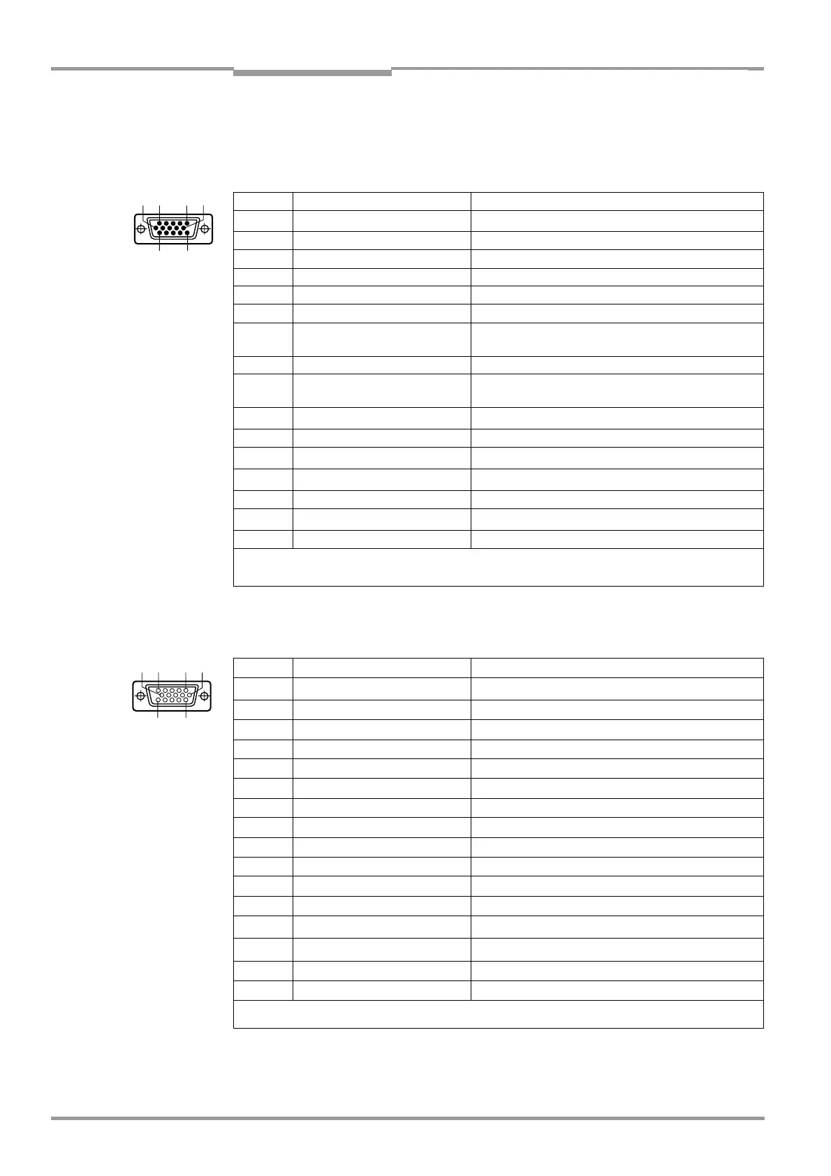
Cable plug: "Host/Term" connection
Cable socket: "I/O" connection
5 6
11
10
15
1
Pin Signal Function
1
1)
V
S
Supply voltage
2 RxD (RS 232), Terminal Terminal interface (receiver)
3 TxD (RS 232), Terminal Terminal interface (transmitter)
4 Term (RS 422/485) Termination host interface
5 GND Ground
6 RD+ (RS 422/485), Host Host interface (receiver+)
7 RD– (RS 422/485), Host
RxD (RS 232), Host
Host interface (receiver–)
8 TD+ (RS 422/485), Host Host interface (transmitter+)
9 TD– (RS 422/485), Host
TxD (RS 232), Host
Host interface (transmitter–)
10
CAN H
2)
CAN interface 1 (IN/OUT)
11 n. c. –
12
CAN2 H
2)3)
CAN interface 2 (IN/OUT)
13
CAN2 L
2)3)
CAN interface 2 (IN/OUT)
14 n. c. –
15
CAN L
2)
CAN interface 1 (IN/OUT)
Housing – Shield
1) Pin 1 is jumpered with Pin 1 of the "I/O" connection in the CLV
2) not connected in no.2 021 689, no. 2 021 298 and no. 2 021 267
3) not connected in no. 2 027 543
Table 5-5: Pin assignment of the 15-pin D Sub HD "Host/Term" cable plug
1 10
15
6
11
5
Pin Signal Function
1
1)
V
S
Supply voltage
2 IN 1 Switching input (trigger for focus control)
3 Sensor Switching input (external reading pulse)
4 Result 1 Switching output, variable function
5 GND Ground
6 IN 0 Switching input (trigger for focus control)
7 IN 2 Switching input (trigger for focus control)
8 Result 2 Switching output, variable function
9 INGND Common ground for all inputs
10 Result 3 Switching output, variable function
11 IN 3 Switching input, variable function
12 IN 4 Switching input, variable function
13
I2C SDA
2)
I2C Bus (for external parameter memory)
14
I2C SCL
2)
I2C Bus (for external parameter memory)
15 Result 4 Switching output, variable function
Housing – Shield
1) Pin 1 is jumpered with Pin 1 of the "Host/Term" connection in the CLV
2) not connected
Table 5-6: Pin assignment of the 15-pin D Sub HD "I/O" cable socket