Chapter 5 Operating Instructions
CLV 480 Bar Code Scanner
5-2 © SICK AG · Division Auto Ident · Germany · All rights reserved 8 010 080/O824/10-02-2005
Electrical installation
5.2 Electrical connections and cables
The electrical connections on the CLV consist of two 15-pin D Sub HD connections on the
housing, one plug, and one socket.
These connections are used to route the following interfaces:
• Three serial data interfaces (host interface, CAN interfaces 1 and 2, terminal interface)
• Six switching inputs (external reading pulse and multifunctional inputs)
• Four switching outputs (for result status function, for connecting to a PLC for example)
• Power supply
5.2.1 Wire cross-sections
CLV without heater:
¾ All connections must be wired with copper cables with a minimum wire diameter of
0.15
mm
2
(approx. 26 AWG)!
CLV with heater:
¾ Connect the power supply terminals (Pin 1/Pin 5) using copper wires with a minimum
cross-section of 0.75 mm
2
(approx. 20 AWG) at a maximum length of 10 m (32.8 ft)!
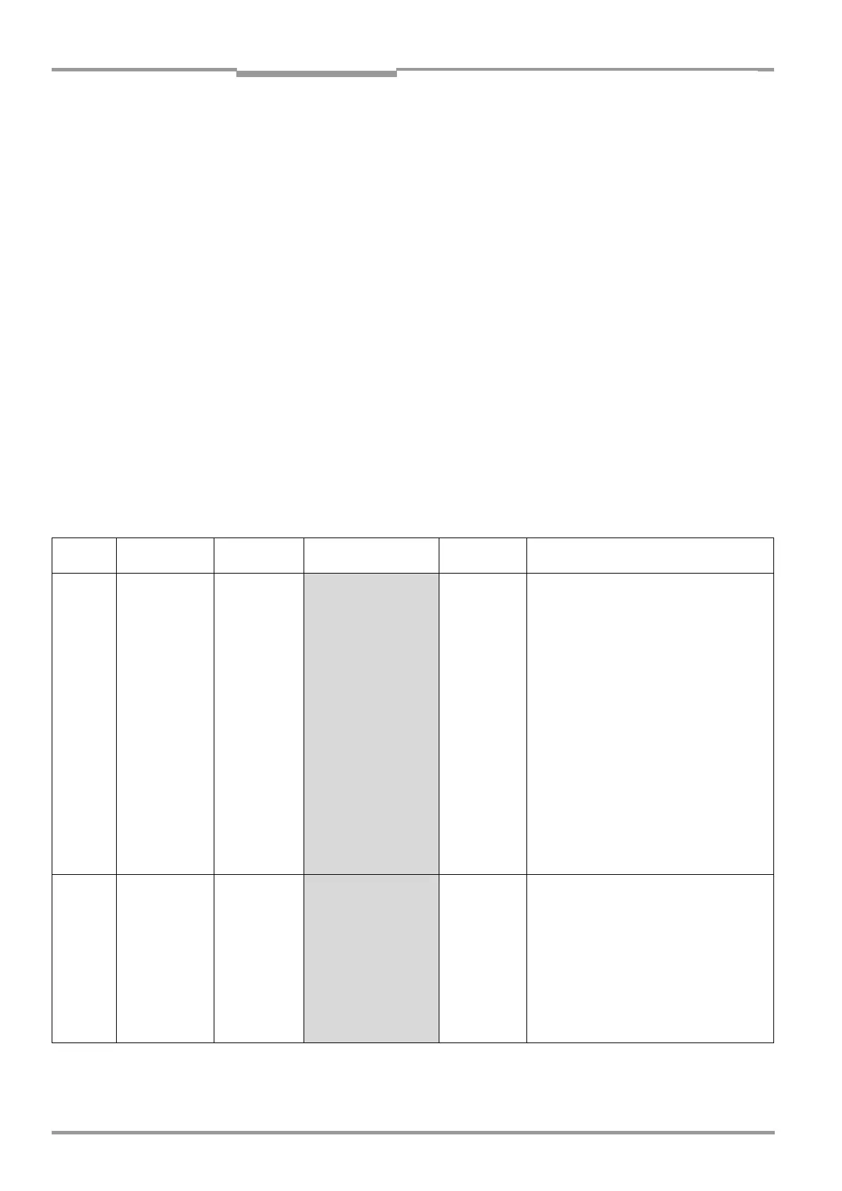
5.2.2 Prefabricated cables (overview)
For technical data on the cables, see Chapter 10.12.4 Cables, external parameter memo-
ries and plug cover, Page 10-53.
CLV
Type
Temperature
range
Connection
module
Optional
cable
Length Type
CLV
without
heater
0 to +40 °C
(+32 to
+104 °F)
AMV/S 60 2 x No. 2 020 302 or
1 x No. 2 020 307
3 m (9.84 in)
3 m (9.84 in)
Connecting cable (plug/socket)
Ext. parameter memory with 2 cables
(plug/socket)
BMV/BMH 10
Bus Connec-
tion Module
1 x No. 2 020 307 or
1 x No. 2 021 298
3 m (9.84 in)
3 m (9.84 in)
Ext. parameter memory with 2 cables
(plug/socket)
Connector cover to connector cover
AMV 30-071 2 x No. 2 020 302 or
1 x No. 2 020 307
3 m (9.84 in)
3 m (9.84 in)
Connecting cable (plug/socket)
Ext. parameter memory with 2 cables
(plug/socket)
BMS 20
Interbus-S
1 x No. 2 020 264 +
1 x No. 2 020 265 or
1 x No. 2 020 308
3 m (9.84 in)
3 m (9.84 in)
3 m (9.84 in)
Connecting cable with plug/open end
Connecting cable with plug/socket
Ext. parameter memory with 2 cables
(plug/open end)
Non-Sick
Power pack
1 x No. 2 020 303 +
1 x No. 2 020 264 or
1 x No. 2 020 981 or
1 x No. 2 021 267
3 m (9.84 in)
3 m (9.84 in)
3 m (9.84 in)
3 m (9.84 in)
Connecting cable with socket/open end
Connecting cable with plug/open end
Ext. parameter memory with 2 cables
(open ends)
Connector cover with 2 cables (open ends)
CLV with
heater
– 35 to +35 °C
(–31 to
+95 °F)
AMV 100 1 x No. 2 021 298 or
1 x No. 2 021 689 or
1 x No. 2 027 543
3 m (9.84 in)
3 m (9.84 in)
3 m (9.84 in)
Connector cover to connector cover
Ext. parameter memory to connector cover
Ext. parameter memory to connector cover
with wires for CAN interface 1 (IN/OUT)
AMV 200 2 x No. 2 021 298 or
2 x No. 2 021 689 or
2 x No. 2 027 543
3 m (9.84 in)
3 m (9.84 in)
3 m (9.84 in)
Connector cover to connector cover
Ext. parameter memory to connector cover
Ext. parameter memory to connector cover
with wires for CAN interface 1 (IN/OUT)
Non-Sick
Power pack
1 x No. 2 021 267 3 m (9.84 in) Connector cover with 2 cables (open ends)
Table 5-2: Cables for connecting the CLV