Operating Instructions Chapter 5
CLV 480 Bar Code Scanner
8 010 080/O824/10-02-2005 © SICK AG · Division Auto Ident · Germany · All rights reserved 5-19
Electrical installation
¾ Connect the sensors as shown in Fig. 5-5.
For connecting the host interface via the AMV/S 60 Connection Module, see the Operating
Instructions "AMV/S 60 Connection Module" (no. 8 008 296).
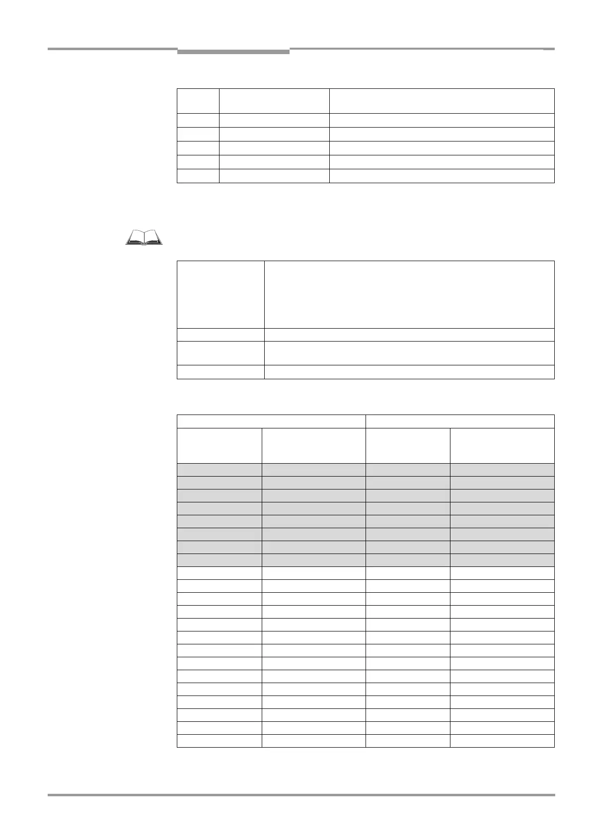
Input
"IN X"
CLV "I/O" connection
Pin Y
AMV/S 60
Terminal Z
IN 0 Pin 6 T. 22
IN 1 Pin 2 T. 23
IN 2 Pin 7 T. 24
IN 3 Pin 11 T. 25
IN 4 Pin 12 T. 26
Table 5-18: Pin and terminal assignment for "IN 0" to "IN 4" switching inputs
Function Trigger source for dynamic focus control
"IN 3" alternative: – trigger source for One Shot on oscillating mirror
"IN 4" alternative: – trigger source for One Shot on oscillating mirror
– encoder increment input
– trigger source for end of reading interval
Default setting "IN 3" and "IN 4": dynamic focus control
Switching mode Active when input energized (high)
Properties – Optodecoupled, non-interchangeable
– Can be connected to PNP output on a sensor
Electrical values
Low: –30 V ≤ V
I
≤ +2 V High: +7 V ≤ V
I
≤ +13 V
Table 5-19: Characteristic data of the "IN 0" to "IN 4" switching inputs
Switching inputs
Content Assignment Table Distance Config.
2)
Logic state
1)
"IN 4 to IN 0"
inputs
Assignment
table index
Default setting Example:
Photoelectric switches
(bright switching)
0 0 0 0 0 N 1 DC 1 DC 6
0 0 0 0 1 N 2 DC 2 DC 5
0 0 0 1 0 N 3 DC 3 DC 4
0 0 0 1 1 N 4 DC 4 DC 4
0 0 1 0 0 N 5 DC 5 DC 3
0 0 1 0 1 N 6 DC 6 DC 3
0 0 1 1 0 N 7 DC 7 DC 3
0 0 1 1 1 N 8 DC 8 DC 3
0 1 0 0 0 N 9 DC 8 DC 2
0 1 0 0 1 N 10 DC 8 DC 2
0 1 0 1 0 N 11 DC 8 DC 2
0 1 0 1 1 N 12 DC 8 DC 2
0 1 1 0 0 N 13 DC 8 DC 2
0 1 1 0 1 N 14 DC 8 DC 2
0 1 1 1 0 N 15 DC 8 DC 2
0 1 1 1 1 N 16 DC 8 DC 2
1 0 0 0 0 N 17 DC 8 DC 1
1 0 0 0 1 N 18 DC 8 DC 1
1 0 0 1 0 N 19 DC 8 DC 1
1 0 0 1 1 N 20 DC 8 DC 1
1 0 1 0 0 N 21 DC 8 DC 1
1 0 1 0 1 N 22 DC 8 DC 1
Table 5-20: Dynamic focus control: switching inputs/distance configuration assignment table