Chapter 5 Operating Instructions
CLV 480 Bar Code Scanner
5-12 © SICK AG · Division Auto Ident · Germany · All rights reserved 8 010 080/O824/10-02-2005
Electrical installation
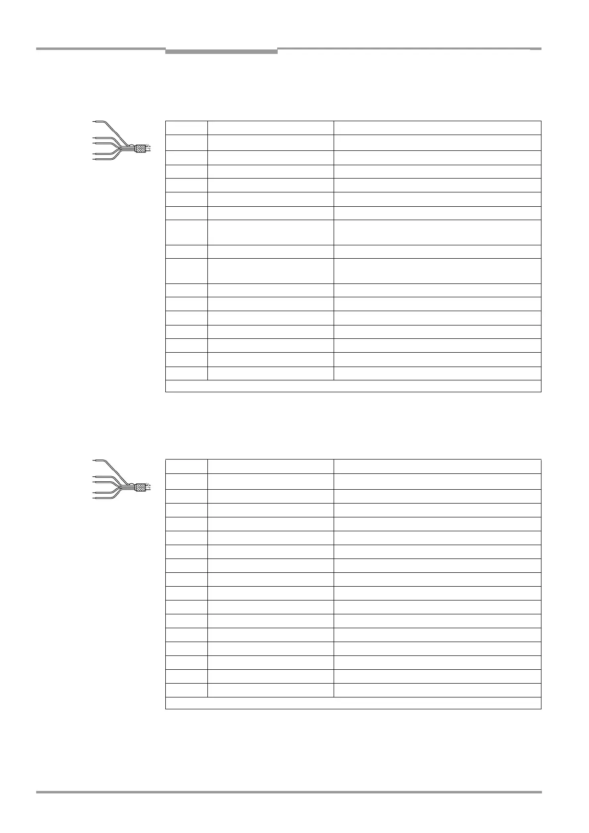
Cable 1 ("Host/Term" connection)
15-pin D Sub HD socket in the connector cover and open cable end
Cable 2 ("I/O" connection)
15-pin D Sub HD plug in the connector cover and open cable end
Pin Signal Wire color
1
1)
V
S
Red and pink
2 RxD (RS 232), Terminal White
3 TxD (RS 232), Terminal Brown
4 Term (RS 422/485) Violet
5 GND Blue and grey-brown
6 RD+ (RS 422/485), Host Green
7 RD– (RS 422/485), Host
RxD (RS 232), Host
Yellow
8 TD+ (RS 422/485), Host Grey
9 TD (RS 422/485), Host
TxD (RS 232), Host
Black
10 CAN H Grey-pink
11 n. c. Red-blue
12 CAN2 H White-green
13 CAN2 L Brown-green
14 n. c. White-yellow
15 CAN L Yellow-brown
– Shield Orange
1) Pin 1 is jumpered with Pin 1 of the "I/O" connection in the CLV
Table 5-12: Wire color assignment of cable 1 for external parameter memory no. 2 020 981
Pin Signal Wire color
1
1)
V
S
Red and pink
2 IN 1 White
3 Sensor Brown
4 Result 1 Violet
5 GND Blue and grey-brown
6 IN 0 Green
7 IN 2 Yellow
8 Result 2 Grey
9 INGND Black
10 Result 3 Grey-pink
11 IN 3 Red-blue
12 IN 4 White-green
13 I2C SDA –
14 I2C SCL –
15 Result 4 Yellow-brown
– Shield Orange
1) Pin 1 is jumpered with Pin 1 of the "Host/Term" connection in the CLV
Table 5-13: Wire color assignment of cable 2 for external parameter memory no. 2 020 981