Operating Instructions Chapter 10
CLV 480 Bar Code Scanner
8 010 080/O824/10-02-2005 © SICK AG · Division Auto Ident · Germany · All rights reserved 10-23
Appendix
10.3.2 Installation and electrical connection
The pin assignments for the connection cables of the parameter memory no. 2 020 307/
no. 2
021 689 are shown in Table 5-5 and Table 5-6, Page 5-8.
¾ Mount the parameter memory on the CLV as shown in Chapter 5.5.3 Connecting the
supply voltage, Page 5-14 and connect the cables to the AMV/S 60 Connection Module.
The color assignment of the wiring for the open ends of the connection cables for the
parameter memory no. 2
020 981 is shown in Table 5-12 and Table 5-13, Page 5-12.
¾ Mount the parameter memory on the CLV as shown in Chapter 5.5.3 Connecting the
supply voltage, Page 5-14 and connect the cables to the external power supply.
10.3.3 Operation
The parameter memory connected to the CLV is accessed
• using the selected CLV start option
• after the parameters have been downloaded to the CLV with the permanent storage
function and the S
TART WITH EXTERNAL PARAMETERS option
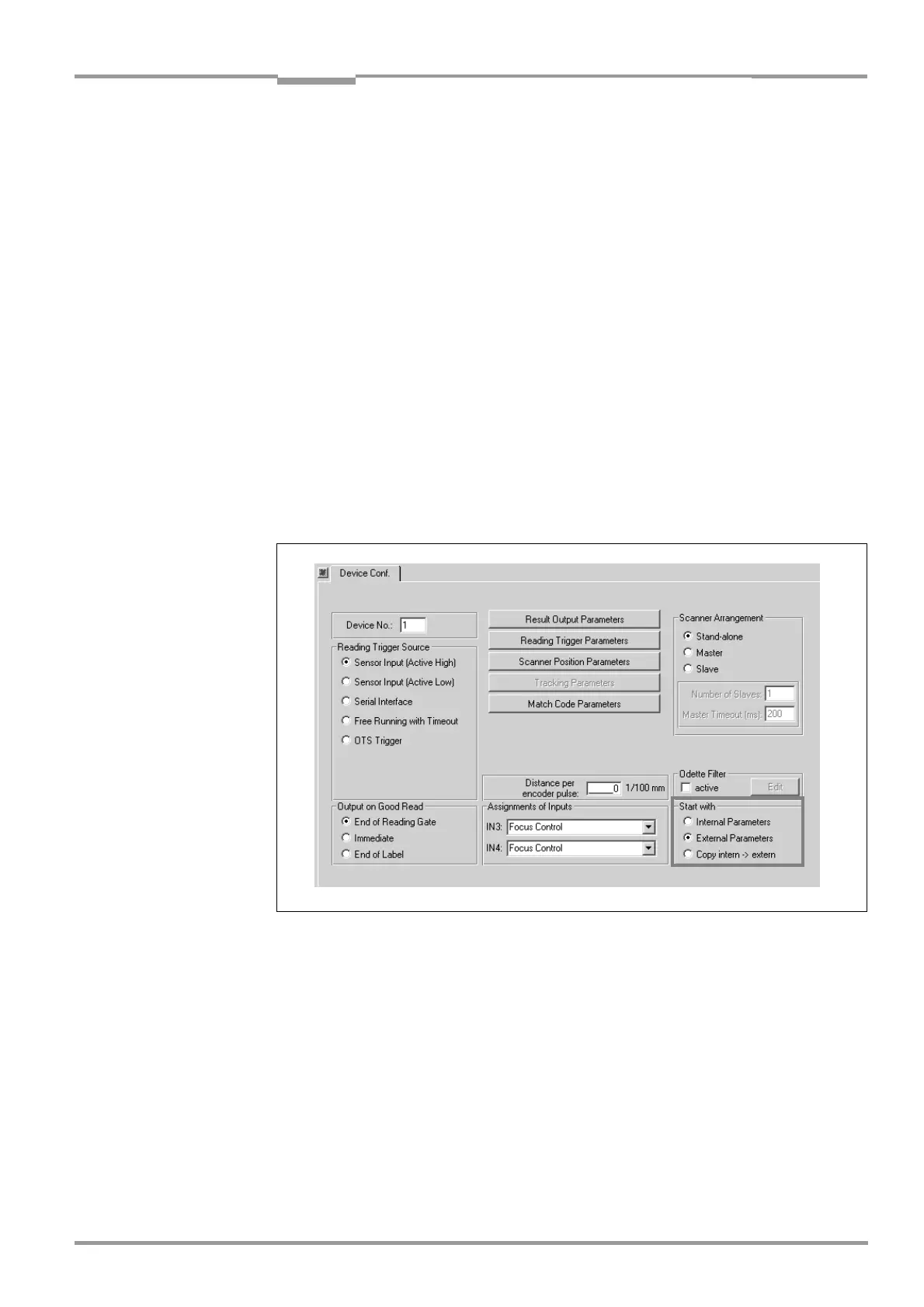
The start option is set at the bottom right of the DEVICE CONFIGURATION tab as shown in
Fig. 10-23 (grey frame). The START WITH EXTERNAL PARAMETERS option is selected by default.
Start with internal parameters
When it starts, the CLV loads the internal parameter set to its RAM.
The "Device Ready" LED lights up constantly.
Since the data is stored permanently, it is not lost when the device is switched off.
Start with external parameters (default setting)
When it starts, the CLV loads the external parameter set to its RAM.
The "Device Ready" LED blinks for approx. 10 s and then lights up constantly.
The data in the CLV is lost when the device is switched off.
Fig. 10-23: CLV-Setup: "Device configuration" tab with the CLV start options