Operating Instructions Chapter 5
CLV 480 Bar Code Scanner
8 010 080/O824/10-02-2005 © SICK AG · Division Auto Ident · Germany · All rights reserved 5-9
Electrical installation
5.4 Preparations for electrical installation
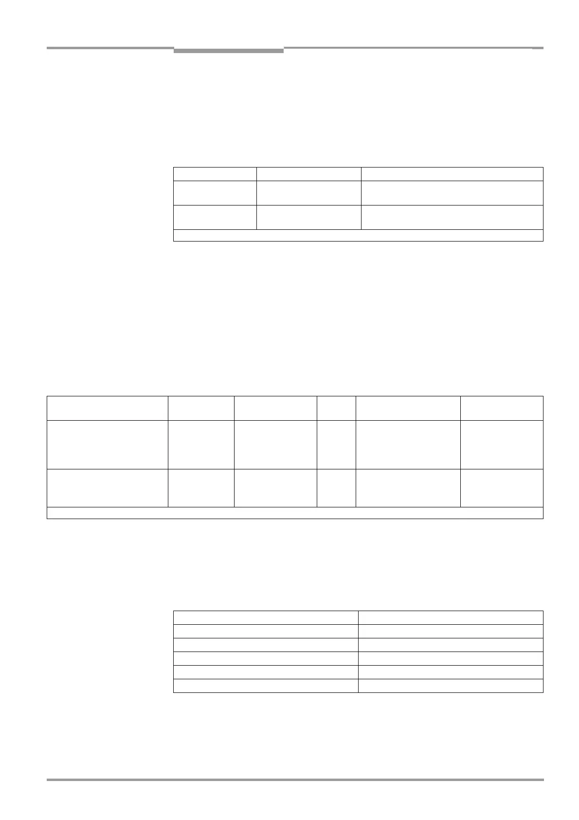
5.4.1 Requirements for the host interface
The host interface of the CLV can be operated as an RS 422/485 or an RS 232 interface.
Table 5-7 shows the recommended maximum cable lengths as a function of the selected
data transfer rate.
¾ To prevent interference, do not lay the cables parallel with power supply and motor
cables over long distances, e. g. in cable ducts.
5.4.2 Supply voltage
The CLV requires a power supply of 18 to 30 V DC for operation without a heater and
24
V DC +20 %/–10 % for operation with a heater (each functional extra-low voltage in
accordance with IEC 364-4-41). The functional extra-low voltage can be generated by using
a safety isloating transformer pursuant to IEC 742.
The power consumption of the individual types is as follows:
Power-up delay
The selected device number (default: 1) affects the power-up delay of the device. This is
useful if a large number of CLVs (e. g. in the SICK network) are to be supplied from one
power source.
Table 5-9 contains a list of the available intervals.
Pin Signal Function
RS 232 Up to 19,200 bd
38 400 to 57,600 bd
Max. 10 m (32.8 ft)
Max. 3 m (9.84 ft)
RS 422/485
1)
Max. 38,400 bd
Max. 57,600 bd
Max. 1 200 m (3 936 ft)
Max. 500 m (1 640 ft)
1) with suitable line termination according to specifications
Table 5-7: Maximum cable lengths between the CLV and host
Type Voltage Scanning method Heater
Power consumption
1)
Connection
module
CLV 480-0010/-2010/-6010 18 to 30 V DC Line scanner No 11 W (typ.)/max. 16 W AMV/S 60 or
CLV 480-1010/-3010/-7010 18 to 30 V DC Line scanner with
oscillating mirror
No 13 W (typ.)/max. 18 W AMV 30-071 or
BMV/BMH 10 or
BMS 20
CLV 480-0011/-2011/-6011 24 V DC Line scanner Yes 75 W (typ.)/max. 90 W AMV 100/200
CLV 480-1011/-3011/-7011 +20 %/–10 % Line scanner with
oscillating mirror
Yes 75 W (typ.)/max. 100 W
1) switching outputs not connected
Table 5-8: Power consumption of the CLV
Device number GN Power-up delay Device number GN Power-up delay
1; 11; 21; 31 0 ms 6; 16; 26 2,000 ms
2; 12; 22 400 ms 7; 17; 27 2,400 ms
3; 13; 23 800 ms 8; 18; 28 2,800 ms
4; 14; 24 1,200 ms 9; 19; 29 3,200 ms
5; 15; 25 1,600 ms 10; 20; 30 3,600 ms
Table 5-9: Power-up delay as a function of the device number GN