Modes 1 to 4 are available. Interference protection influences the scan cycle time and
t
herefore the response time.
•
Mode 1 = + 0 ms per scan cycle
•
Mode 2 = + 1 ms per scan cycle
•
Mode 3 = + 2 ms per scan cycle
•
Mode 4 = + 3 ms per scan cycle
b
Configure a different mode for each safety laser scanner that is mounted in close
proximity.
✓
The resulting response time is shown.
Complementary information
NOTE
The response time of the safety laser scanner depends on the scan cycle time, interfer‐
ence protection, and multiple sampling, see "Response times", page 172. In addition
to the response time of the safety laser scanner, further signal transmission and
processing also influence the time until the end of the dangerous state.
A graphic shows how the configuration affects the available ranges.
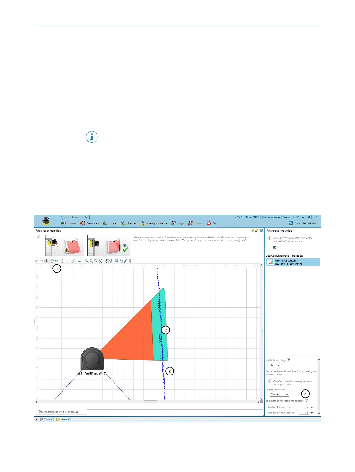
7.10 Reference contour field
Overview
Figure 67: Reference contour field
1
Tool for drawing reference contour fields
CONFIGURATION 7
8021219/1ELL/2022-01-21 | SICK O P E R A T I N G I N S T R U C T I O N S | microScan3 – PROFINET
105
Subject to change without notice