5 10 20 50
R [%]
500
200
100
50
20
10
5
2
1
6
5
3
2
4
1
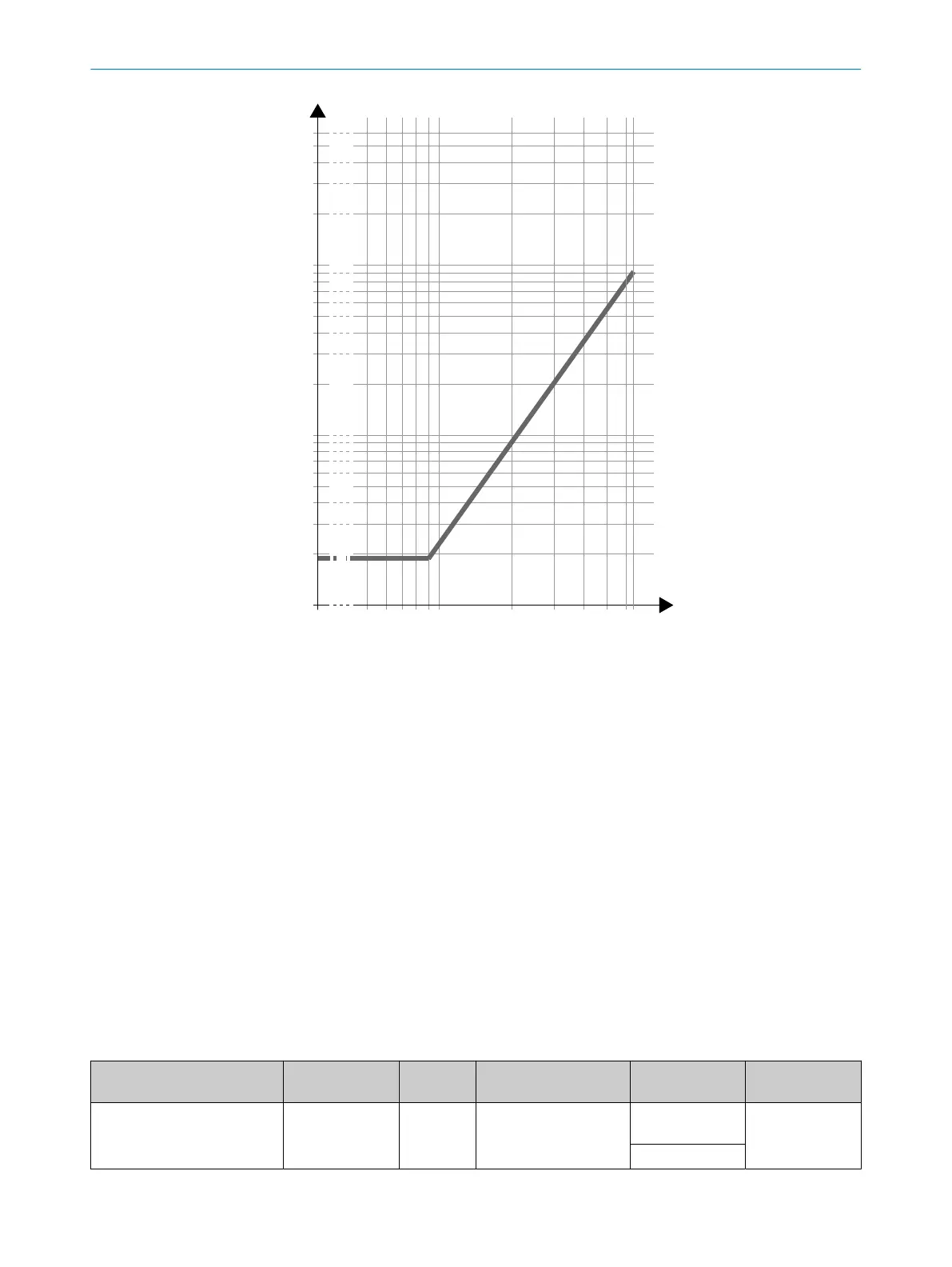
64 D [m]
Figure 97: Scanning range and required remission for warning fields (devices with a max.
pr
otective field range of 9.0 m)
R Required minimum remission in %
D Scanning range in m
1
Black shoe leather
2
Matt black paint
3
Gray cardboard
4
Writing paper
5
White plaster
6
Reflectors > 2,000%, reflective tapes > 300%
13.6 Data exchange in the network
13.6.1 Process images in detail
13.6.1.1 Available data
13.6.1.1.1 Input of the device (output of the control)
Table 49: Input of the device (output of the control)
Name Use Data type Definition Values Safety implica‐
t
ion
ActivateStandbyMode Additional func‐
tion
BOOL Activate sleep mode
Activates sleep mode.
0 = no sleep
mode
Parameter with‐
out safety impli‐
cation
1 = sleep mode
TECHNICAL DATA 13
8021219/1ELL/2022-01-21 | SICK O P E R A T I N G I N S T R U C T I O N S | microScan3 – PROFINET
177
Subject to change without notice