11.4.5 PROFINET Status
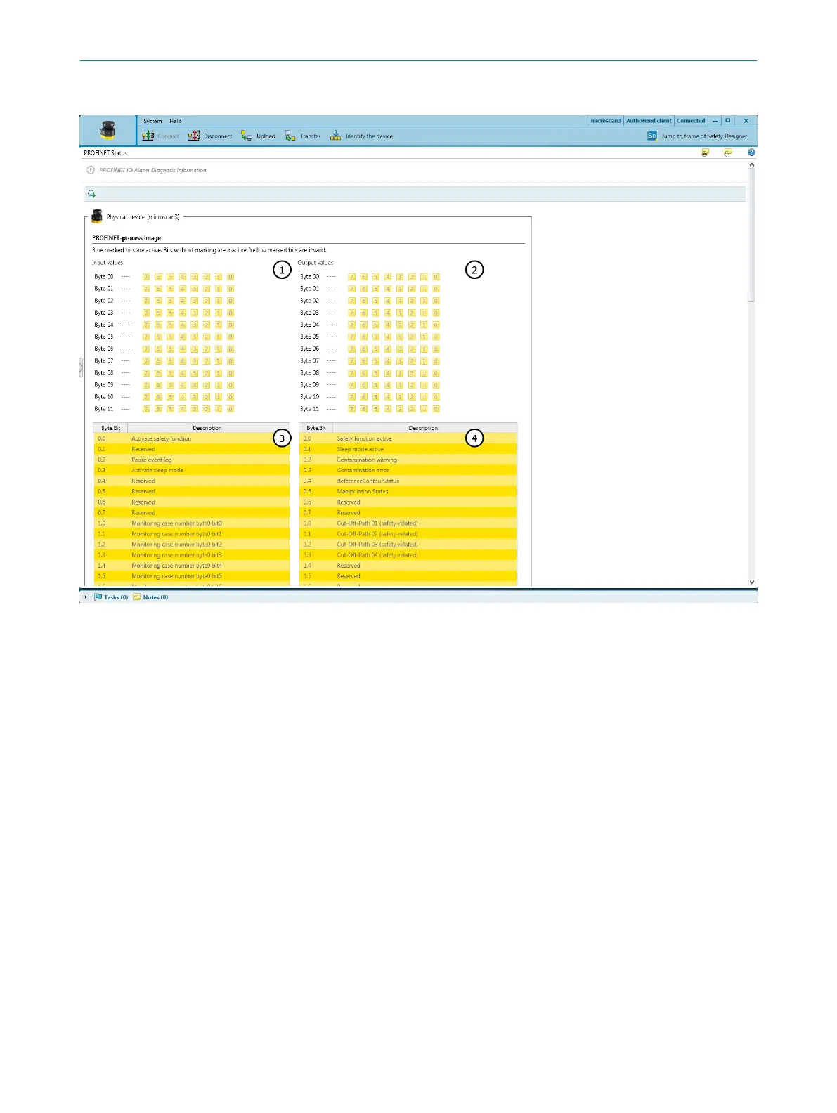
Figure 93: PROFINET status
1
Data at the input of the safety laser scanner (controller output), graphical
2
Data at the output of the safety laser scanner (controller input), graphical
3
Data at the input of the safety laser scanner (controller output), tabular
4
Data at the output of the safety laser scanner (controller input), in tabular form
When you click on the clock icon, Safety Designer displays the input data (from the
per
spective of the safety laser scanner) and the output data (from the perspective of
the safety laser scanner).
In the upper part, the data is divided into bits and bytes.
In the lower part, the bits are displayed in tabular form with a description.
The colors have the following meanings:
•
Gray: Bit is not active
•
Blue: Bit is active
•
Yellow: bit is invalid
11.5 Diagnostics using the control
The control allows you to access the contents of the process map, I&M data and
alar
ms, see "Available data", page 69.
TROUBLESHOOTING 11
8021219/1ELL/2022-01-21 | SICK O P E R A T I N G I N S T R U C T I O N S | microScan3 – PROFINET
159
Subject to change without notice