microScan3 – PROFINET (M12)
V
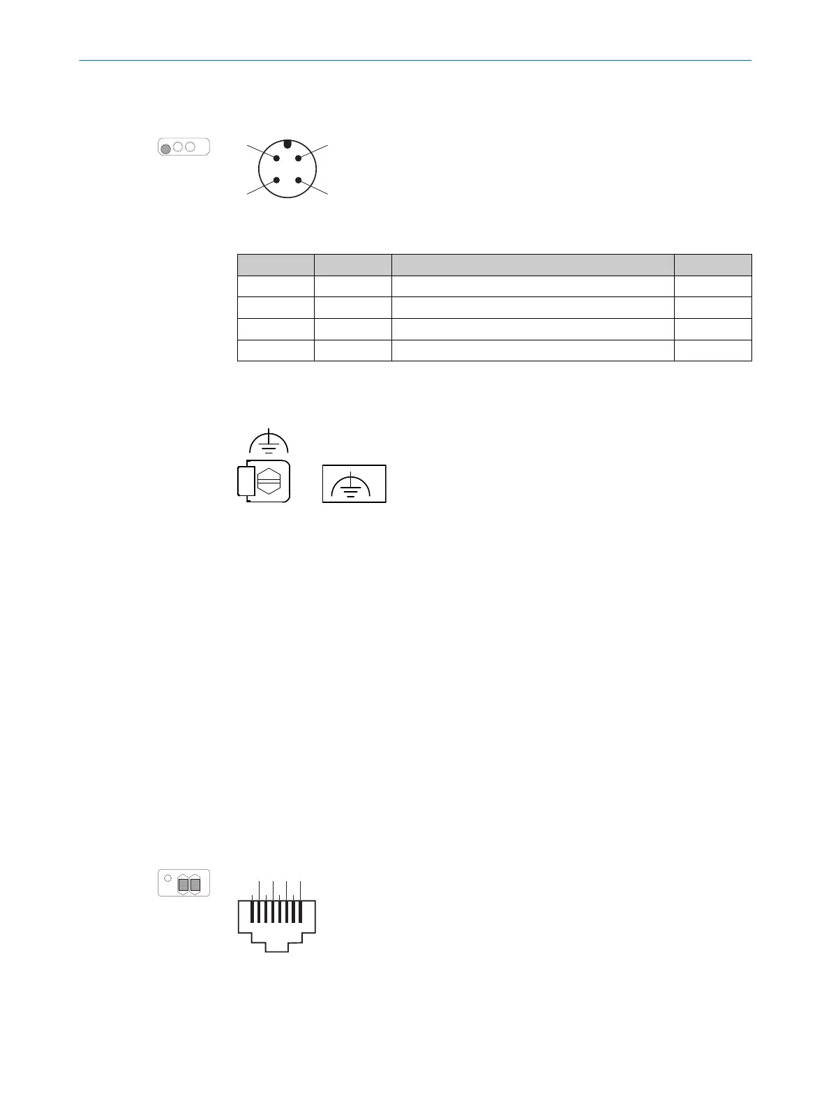
oltage supply is supplied via a 4-pin, A-coding M12 male connector on the device side.
Figure 52: Pin assignment of the voltage supply (male connector, M12, 4-pin, A-coded)
Table 8: Pin assignment of the voltage supply
Pin Marking Function Wire color
1)
1 +24 V DC 24 V DC supply voltage Brown
2 nc Not connected White
3 0 V DC 0 V DC supply voltage Blue
4 FE Functional earth/shield Black
1)
Applies to the connecting cables recommended as accessories.
6.3.2 Alternative FE connection
Figure 53: Alternative FE connection
Screw connection of the alternative FE connection
•
Screw: M5 × 12
•
Screw head: hexagon with slot, width across flats WAF 8
•
Tightening torque: 3.5 Nm to 5.0 Nm
Suitable cable lugs
•
Forked cable lug or ring cable lug
•
Width ≤ 10 mm
•
Hole diameter for screw: typically 5.2 mm
Older system plugs (older than roughly September 2019) might not have an alternative
FE c
onnection.
6.3.3 Ethernet for PROFINET PROFIsafe, data output, configuration and diagnostics (XF1, XF2)
microScan3 – PROFINET (RJ45)
On t
he device side, Ethernet and PROFINET are connected via RJ45 female connectors
for push-pull connectors. There is a network switch in the safety laser scanner which
connects the two female connectors. The two female connectors therefore have the
same function.
Figure 54: Network pin assignment (female connector, RJ45, for push-pull male connector)
ELECTRICAL INSTALLATION 6
8021219/1ELL/2022-01-21 | SICK O P E R A T I N G I N S T R U C T I O N S | microScan3 – PROFINET
83
Subject to change without notice