Table 9: Network pin assignment
Pin Designation Function
1 TX+ Send data +
2 TX– Send data –
3 RX+ Receive data +
4 – Reserved
5 – Reserved
6 RX– Receive data –
7 – Reserved
8 – Reserved
Housing SH Shielding
microScan3 – PROFINET (SCRJ)
On t
he device side, Ethernet and PROFINET are connected via SCRJ female connectors
for push-pull connectors. There is a network switch in the safety laser scanner which
connects the two female connectors. The two female connectors therefore have the
same function.
Figure 55: Network pin assignment (female connector, SCRJ, for push-pull male connector)
Table 10: Network pin assignment
Pin Designation Function
1 TX Send data
2 RX Receive data
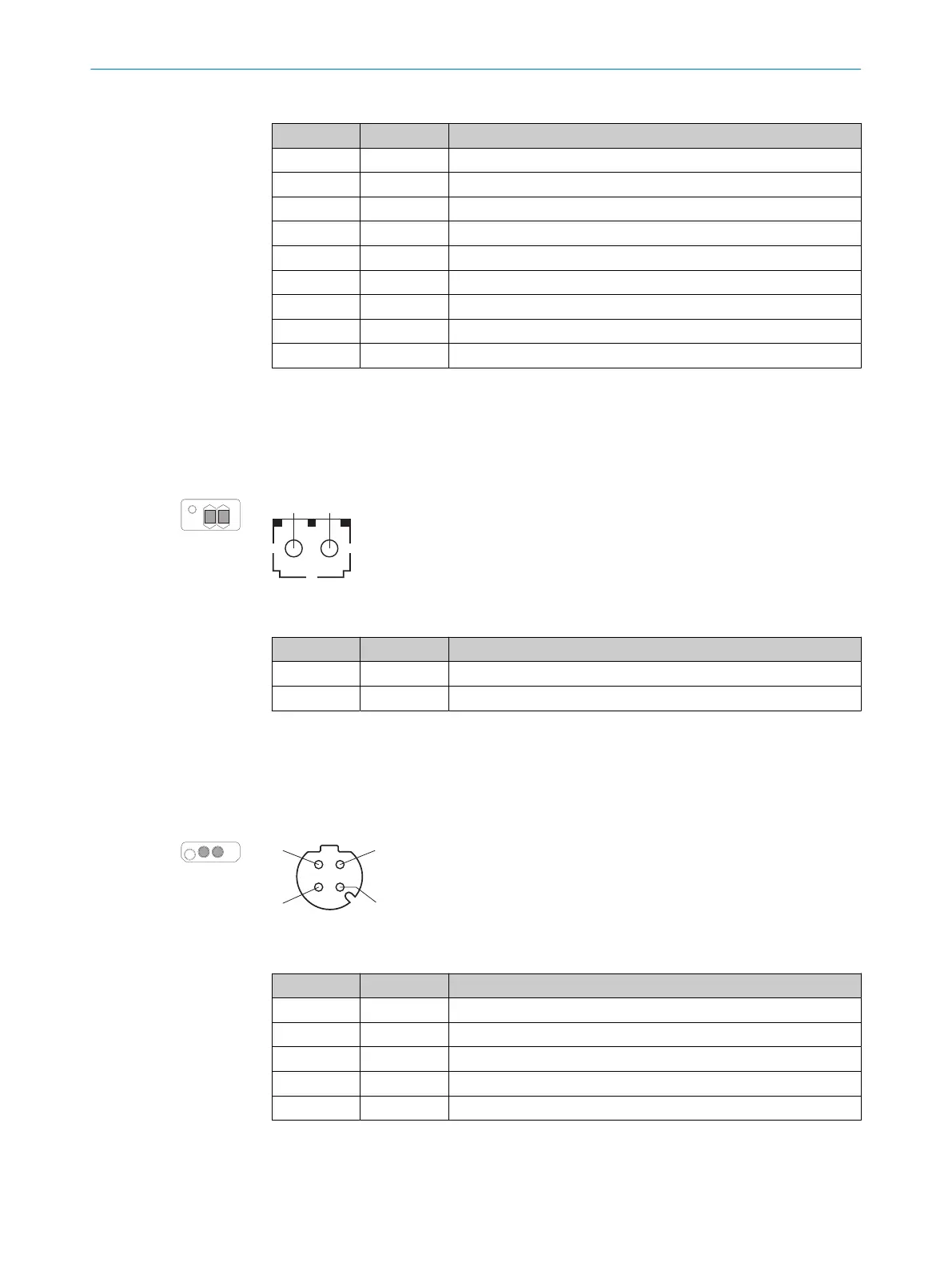
microScan3 – PROFINET (M12)
On t
he device side, Ethernet and PROFINET are connected via 4-pin, D-coded M12
female connectors. There is a network switch in the safety laser scanner which con‐
nects the two female connectors. The two female connectors therefore have the same
function. The pin assignment corresponds to EN 61918, Appendix H.
Figure 56: Network pin assignment (M12 female connector, 4-pin, D-coding)
Table 11: Network pin assignment
Pin Designation Function
1 TX+ Send data +
2 RX+ Receive data +
3 TX– Send data -
4 RX– Receive data -
Thread SH Shielding
6 ELECTRICAL INSTALLATION
84
O P E R A T I N G I N S T R U C T I O N S | microScan3 – PROFINET 8021219/1ELL/2022-01-21 | SICK
Subject to change without notice