7.12 Inputs and outputs
Overview
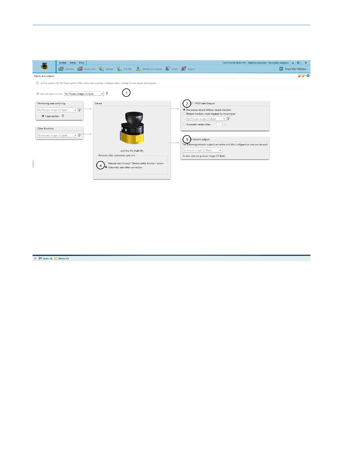
Figure 74: Inputs and outputs
1
Input source
2
Restart behavior of the network outputs
3
Network outputs
4
Behavior after connection gets lost
Safety Designer provides a selection of the possible signal inputs.
Use one input source
Y
ou specify which process image is to be used.
The selected process image is used by the safety laser scanner as the input source
for monitoring case switching, for the reset signal, and for other functions (restart the
device or activate the sleep mode).
For its output data, the safety laser scanner automatically uses the process image that
corresponds to the process map chosen as the input source (same length).
The process image chosen here must have the same length (6 bytes or 12 bytes) as the
process image configured in the controller for the safety laser scanner.
Behavior after connection gets lost
If t
he PROFIsafe communication is reestablished after an interruption, the controller
must be reintegrated.
7 C
ONFIGURATION
118
O P E R A T I N G I N S T R U C T I O N S | microScan3 – PROFINET 8021219/1ELL/2022-01-21 | SICK
Subject to change without notice