EasyManuals Logo

SICK microScan3 User Manual

SICK microScan3
212 pages
To Next Page IconTo Next Page
To Previous Page IconTo Previous Page
Page #124 background imageLoading...
Page #124 background image
Simulation components and options
Dis
play the status of the cut-off paths
You can switch monitoring cases virtually and observe the result
You can mark a field in the simulation as interrupted and check which result is
triggered by an object in the relevant field
You can move fields to the foreground or to the background using the context
menu (right mouse button)
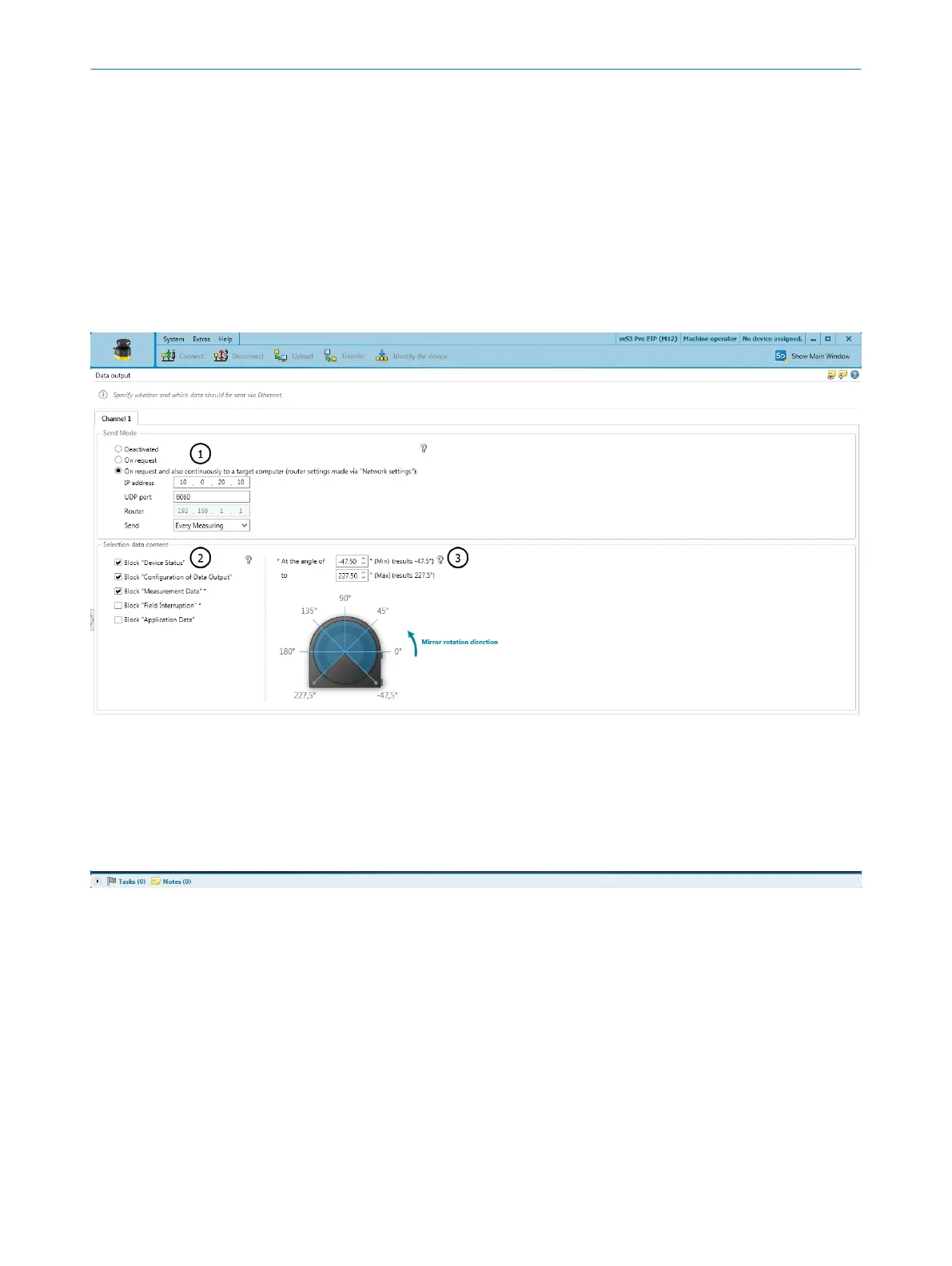
7.15 Data output
Overview
Figure 77: Data output
1
Send mode
2
Data content
3
Angular range
You can define which data from the safety laser scanner is to be output via UDP or
T
CP/IP.
7 C
ONFIGURATION
124
O P E R A T I N G I N S T R U C T I O N S | microScan3 – PROFINET 8021219/1ELL/2022-01-21 | SICK
Subject to change without notice

Table of Contents

Other manuals for SICK microScan3

Questions and Answers:

Question and Answer IconNeed help?

Do you have a question about the SICK microScan3 and is the answer not in the manual?

SICK microScan3 Specifications

General IconGeneral
Scanning angle275°
Power supply24 V DC
Supply voltage24 V DC ± 20%
Enclosure ratingIP65
Resolution70 mm
Protective field range5.5 m
Number of fields128
InterfaceEthernet
Safety integrity levelSIL3
Performance levelPL e
Ambient temperature+50°C
Scanning range5.5 m

Related product manuals