3 Product description
3.1 Device overview
Overview
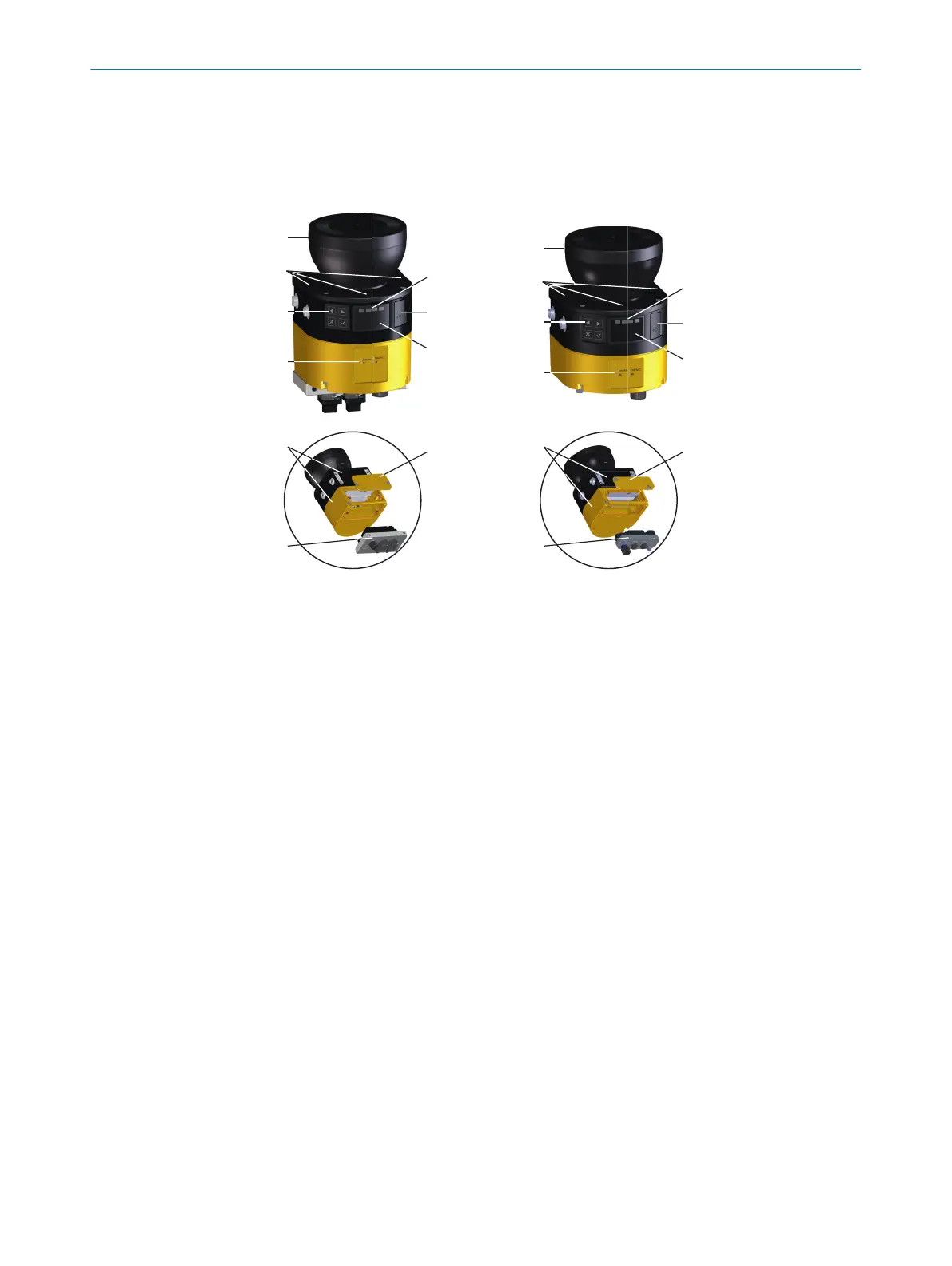
Figure 2: Device overview (
left: microScan3 – PROFINET (RJ45 / SCRJ), right: microScan3 –
PROFINET (M12))
1
Optics cover
2
Display
3
Keypad
4
USB connection
5
Status LEDs
6
Additional LEDs for ON state and OFF state
7
Network LEDs
8
Safety laser scanner without system plug
9
System plug
ß
Cover plate
Complementary information
T
he safety laser scanner can be mounted and operated in any orientation.
Position and direction information in this document:
•
The top is the side of the safety laser scanner on which the optics cover is located.
•
The bottom is the side of the safety laser scanner opposite the optics cover.
•
The front is the side of the safety laser scanner on which the display is located.
The 90° angle of the sector of a circle scanned by the safety laser scanner points
in this direction.
•
The back is the side of the safety laser scanner opposite the display. The sector of
a circle not scanned by the safety laser scanner lies in this direction.
Further topics
•
"C
onnections", page 16
•
"Status indicators", page 136
PRODUCT DESCRIPTION 3
8021219/1ELL/2022-01-21 | SICK O P E R A T I N G I N S T R U C T I O N S | microScan3 – PROFINET
13
Subject to change without notice