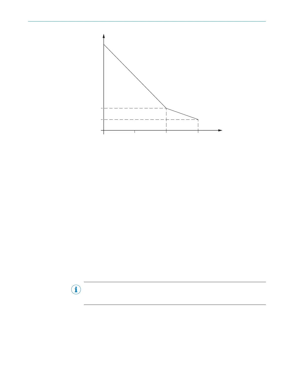
Figure 35: Minimum supplement for lack of ground clearance
B
F
ground clearance in mm
Z
F
supplement for lack of ground clearance in mm
Calculation example for the protective field length S
L
S
L
= S
A
+ T
Z + Z
R
+ Z
F
+ Z
B
where:
•
S
L
= protective field length in millimeters (mm)
•
S
A
= stopping distance in millimeters (mm)
•
TZ = tolerance range of the safety laser scanner, see "Data sheet", page 165
•
Z
R
= supplement for reflection-based measurement errors in millimeters (mm)
•
Z
F
= supplement for lack of ground clearance of the vehicle in millimeters (mm)
•
Z
B
= supplement for the decreasing braking force of the vehicle, from the vehicle
documentation, in millimeters (mm)
Stopping distance S
A
T
he stopping distance comprises the vehicle’s braking distance and the distance cov‐
ered during the safety laser scanner’s response time and the vehicle control’s response
time (including signal propagation time).
NOTE
A v
ehicle’s braking distance does not increase linearly with increasing speed, but rather
in a squared relationship.
PROJECT PLANNING 4
8021219/1ELL/2022-01-21 | SICK O P E R A T I N G I N S T R U C T I O N S | microScan3 – PROFINET
49
Subject to change without notice