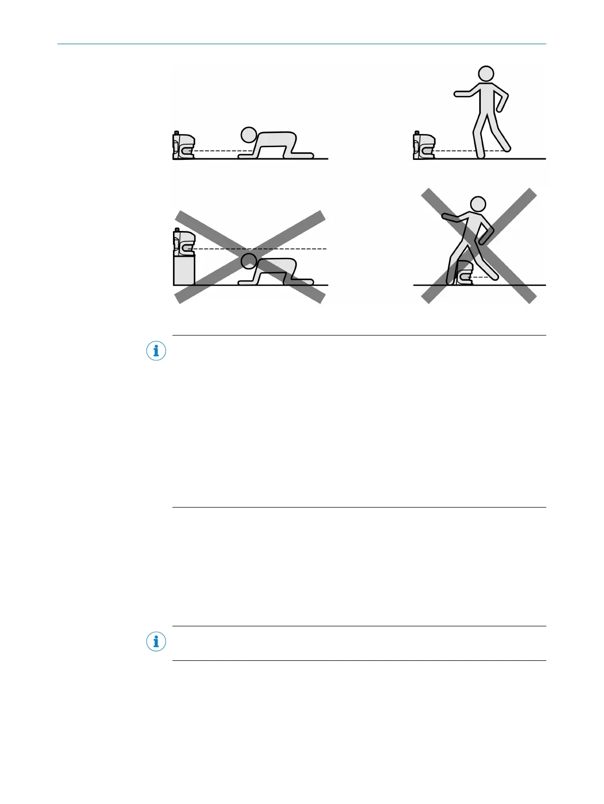
Figure 40: Prevent crawling beneath, standing behind, or climbing over
NOTE
b
Mount t
he device so that it is protected from moisture, dirt, and damage.
b
Mount the sensor so that the status indicators can be clearly seen.
b
Always mount the device so that there is still enough space for mounting and dis‐
mantling the system connector.
b
Avoid exposing the device to excessive shock and vibration.
b
For systems that vibrate heavily, use shock absorbers to prevent the possibility of
fixing screws unintentionally coming loose.
b
Regularly check the tightness of the fixing screws.
b
Observe the maximum permissible tightening torque for the fixing screws on the
device:
°
M6 at the rear = max. 12 Nm
°
M8 side = max. 16 Nm
Further topics
•
"Dimensional dr
awings", page 121
•
"Brackets", page 125
5.2.1 Direct mounting
The device has four M6 × 8 threaded holes on the rear. They can be used to mount the
de
vice directly if you are able to drill through the mounting surface from behind.
NOTE
T
he maximum permissible tightening torque of the threaded holes is 12 Nm.
5 MOUNTING
52
O P E R A T I N G I N S T R U C T I O N S | S3000 PROFINET IO, S3000 PROFINET IO-OF 8013291/ZA19/2019-11-14 | SICK
Subject to change without notice