WARNING
P
ersons or parts of the body to be protected may not be recognized or not recognized in
time in case of non-observance.
The protective field suggested by the CDS is not a replacement for the calculation of the
minimum distance, see "Mounting", page 50.
Before commissioning the machine or vehicle, check the configuration of the protective
fields, see "Commissioning", page 88, see "Checklist for initial commissioning and
commissioning", page 133.
b
Calculate the minimum distance.
b
Check the configured protective fields.
7.10.4 Using the contour as a reference
In addition to the protective field, the device can also monitor a contour (e.g., the floor
in v
ertical applications).
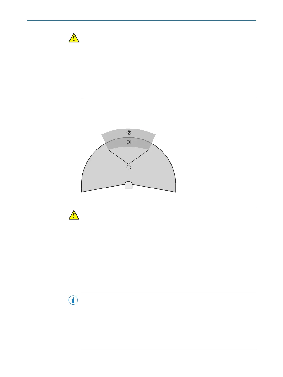
Figure 64: Schematic diagram of contour as reference
WARNING
D
angerous state of the machine
If a contour segment is smaller than the configured resolution, a change in the contour
or a change in the position of the device may not be detected.
b
Define contour segments that are larger than the configured resolution.
For contour monitoring you define a contour segment 1. T
he contour segment com‐
prises a positive 2 and a negative 3 tolerance band.
The device signals Protective field interrupted in the following situations:
•
There is an object in the protective field.
•
The monitored surrounding contour is no longer in the tolerance band, e.g., if a
door is opened or the position of the safety laser scanner is changed.
NOTE
•
Y
ou can define any number of contour segments.
•
You cannot define warning fields at the points where a contour has been config‐
ured as a reference. If, for example, you use the floor as a reference for access
protection, you cannot configure a warning field there. However, you can for exam‐
ple configure a warning field to the left and right of the contour segment to control
a warning signal on approach from the side.
•
The contour as reference function and the warning field 2 function are mutually
exclusive.
7 C
ONFIGURATION
82
O P E R A T I N G I N S T R U C T I O N S | S3000 PROFINET IO, S3000 PROFINET IO-OF 8013291/ZA19/2019-11-14 | SICK
Subject to change without notice