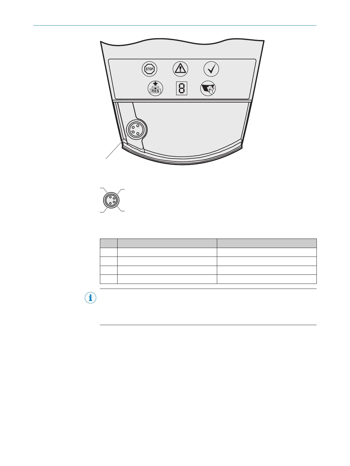
Figure 51: Local configuration connection
Figure 52: Pin assignment on the M8 × 4 configuration connection
T
able 9: Pin assignment on the M8 × 4 configuration connection
Pin Safety laser scanner PC-side RS232 DSub
1 Reserved Not assigned
2 RxD Pin 3
3 0 V DC input (power supply) Pin 5
4 TxD Pin 2
NOTE
b
Pull t
he connection cable out of the configuration connection after configuration.
b
After the device has been configured, plug the protective cap fastened to the
device back into the configuration connection.
6 ELECTRICAL INSTALLATION
64
O P E R A T I N G I N S T R U C T I O N S | S3000 PROFINET IO, S3000 PROFINET IO-OF 8013291/ZA19/2019-11-14 | SICK
Subject to change without notice