4.5.4 Terminal strips
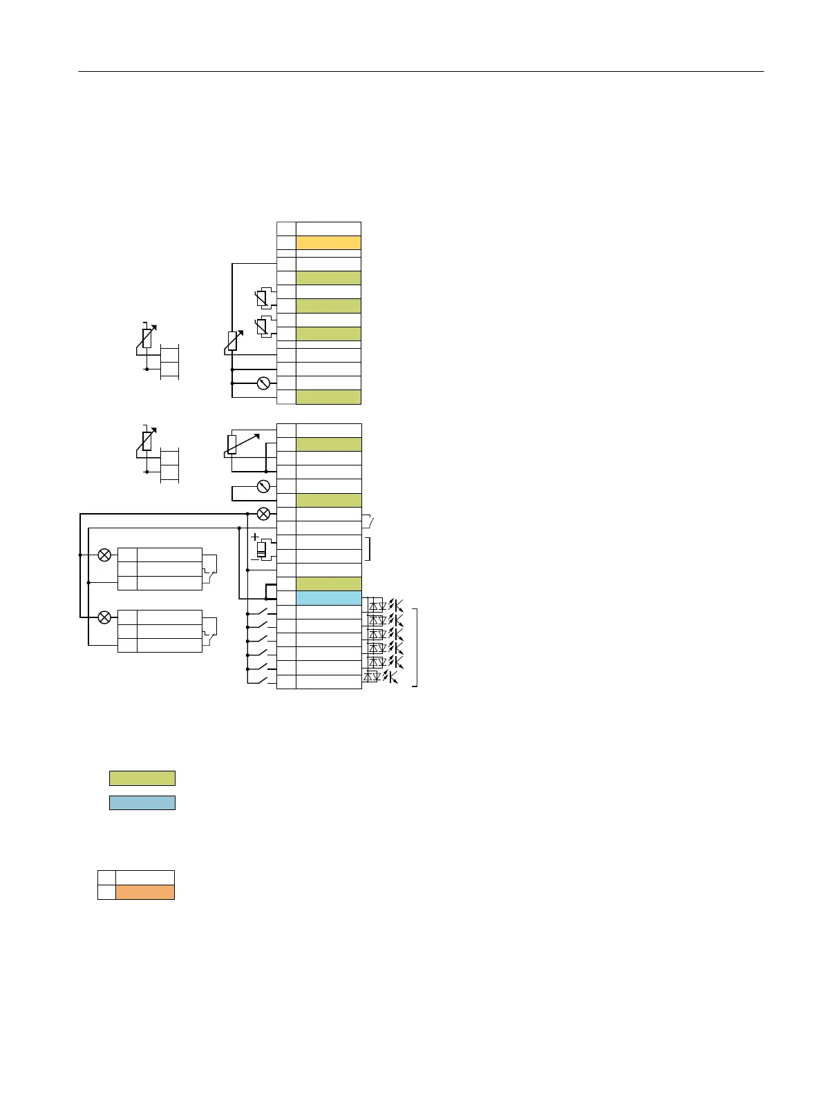
Terminal strips with wiring example
99RSWLRQDOSRZHUVXSSO\
5HIHUHQFHIRUWHUPLQDO
9RXWSXWPD[P$
$QDORJLQSXW99P$P$
5HIHUHQFHIRUWHUPLQDO
$QDORJLQSXW99P$P$
5HIHUHQFHIRUWHUPLQDO
$QDORJRXWSXW9ಹ9P$ಹP$
$QDORJRXWSXW9ಹ9P$ಹP$
9RXWSXWPD[P$
5HIHUHQFHIRUWHUPLQDOVDQG
5HIHUHQFHIRUWHUPLQDOVDQG
5HIHUHQFHIRUWHUPLQDOVDQG
5HIHUHQFHIRUWHUPLQDOVDQG
5HIHUHQFHIRUWHUPLQDOVDQG
5HIHUHQFHIRUWHUPLQDOVDQG
5HIHUHQFHIRUWHUPLQDOVDQG
6HQVRU3W/*1LRUDQDORJLQSXW
6HQVRU3W/*1L
'LJLWDORXWSXWPD[$9'&
5HIHUHQFHIRUGLJLWDOLQSXWV
9RXWSXWPD[P$
'LJLWDORXWSXWV
PD[$9'&
$9$&
7HPSHUDWXUHVHQVRU37&.7<3WELPHWDOOLF
'LJLWDOLQSXWV
IRUFRQQHFWLRQ3RU0VZLWFKLQJFRQWDFW
ORZ9KLJK!9PD[9
9,1
*1',1
$,
$,
$2
*1'
*1'
9RXW
*1'
$,1,
*1'
$,1,
9RXW
*1'
$,
$,
$2
*1'
'212
'2&20
702725
702725
9RXW
*1'
',&20
',
',
',
',
',
',
9
H[W
*1'
H[W
9
H[W
*1'
H[W
'212
'2&20
'21&
'212
'2&20
'21&
;
;
;
;
ุN˖
ุN˖
1)
The following applies to systems compliant with UL: Maximum current, 3 A 30 VDC or 2 A 250 VAC
Figure 4-29 Wiring the digital inputs with p-switching contacts and an internal 24 V power supply (terminal 9)
All terminals labelled with reference potential "GND" are connected internally in the inverter.
Reference potential "DI COM" is electrically isolated from "GND". The Control Unit is delivered
with a jumper between terminals 28 and 69.
→ If, as shown above, you wish to use the 24‑V supply from terminal 9 as supply for the digital
inputs, then it is mandatory that this jumper is used.
When an optional 24 V power supply is connected at terminals 31, 32, even when the Power
Module is disconnected from the line supply, the Control Unit remains in operation. The Control
Unit thus maintains fieldbus communication, for example.
→ for terminals 31, 32 only use a 24 VDC power supply with PELV (Protective Extra Low
Voltage).
→ for applications in the USA and Canada: Use a 24 VDC power supply, NEC Class 2.
Installing
4.5 Connecting the interfaces for the inverter control
Converter with the CU230P-2 Control Units
Operating Instructions, 09/2017, FW V4.7 SP9, A5E34257946B AE 111

 Loading...


