4.3.2 Dimension drawings, drilling dimensions for the PM230 Power Module, IP55
The following dimension drawings are not to scale.
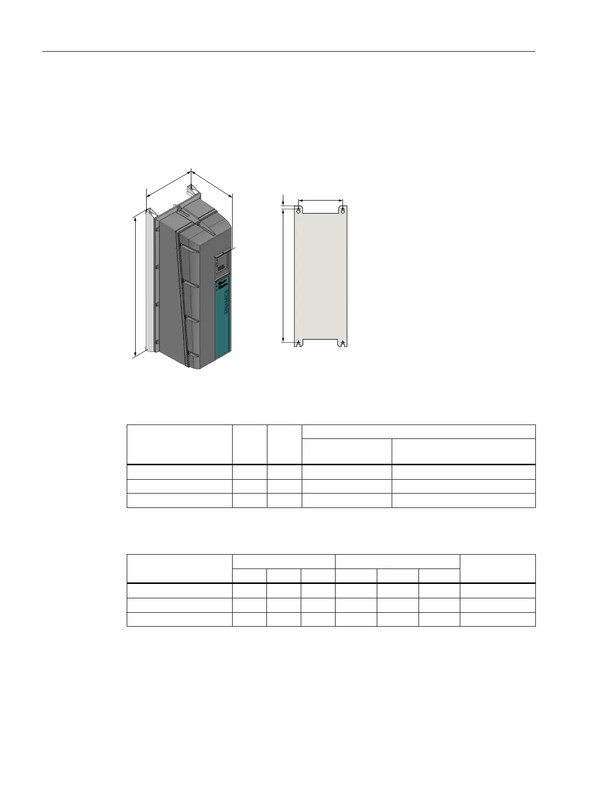
Frame sizes FSA ... FSC
Figure 4-5 Dimension drawing, PM230 Power Module IP55, FSA … FSC
Table 4-1 Dimensions
Frame size Width
[mm]
Height
[mm]
Depth [mm]
Without operator
panel
With BOP‑2, IOP‑2 operator panel
or blanking cover
FSA 154 460 249 256
FSB 180 540 249 256
FSC 230 620 249 256
Table 4-2 Drilling dimensions, cooling clearances and fixing
Frame size Drilling dimensions [mm] Cooling air clearances [mm] Screws/torque
[Nm]
b h c Top Bottom Lateral
FSA 132 445 11 100 100 0
1)
4 x M4 / 2.5
FSB 158 524 11 100 100 0
1)
4 x M4 / 2.5
FSC 208 604 11 125 125 0
1)
4 x M5 / 3.0
1)
You can mount the Power Modules without any lateral cooling air clearance. For tolerance reasons,
we recommend a lateral clearance of approx. 1 mm.
Installing
4.3 Installing Power Modules
Converter with the CU230P-2 Control Units
66 Operating Instructions, 09/2017, FW V4.7 SP9, A5E34257946B AE

 Loading...


