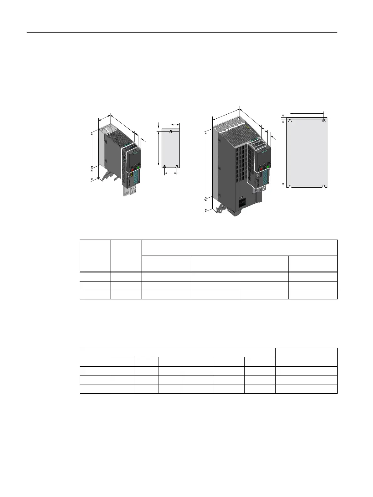
4.3.6 Dimensioned drawings, drilling dimensions for the PM240-2 Power Module, IP20
The following dimension drawings and drilling patterns are not to scale.
Frame sizes FSA ... FSC
+HLJKWZLWKRXW
VKLHOGSODWH
:LGWK
'HSWK
6KLHOGSODWH
+HLJKWZLWKRXWVKLHOG
SODWH
:LGWK
'HSWK
&8
23
6KLHOG
SODWH
)6$
&8
23
KF
E
KF
E
)6%)6&
Table 4-12 Dimensions depend on the operator panel (OP) that is inserted
Frame
size
Width
[mm]
Height [mm] Mounting depth in the cabinet with
Control Unit (CU) [mm]
2)
without shield
plate
with shield plate without OP with OP
1)
FSA 73 196 276 224 235
FSB 100 292 370 224 235
FSC 140 355 432 224 235
1)
BOP-2, IOP-2 or blanking cover
2)
Power Module depth without Control Unit: 165 mm
Table 4-13 Drilling dimensions, cooling clearances and fixing
Frame
size
Drilling dimensions [mm] Cooling air clearances [mm]
1)
Fixing/torque [Nm]
h b c Top Bottom Front
FSA 186 62.3 6 80 100 100 3 x M4 / 2.5
FSB 281 80 6 80 100 100 4 x M4 / 2.5
FSC 343 120 6 80 100 100 4 x M5 / 3.5
1)
The Power Module is designed for mounting without any lateral cooling air clearance. For tolerance
reasons, we recommend a lateral clearance of approx. 1 mm.
Installing
4.3 Installing Power Modules
Converter with the CU230P-2 Control Units
74 Operating Instructions, 09/2017, FW V4.7 SP9, A5E34257946B AE

 Loading...


