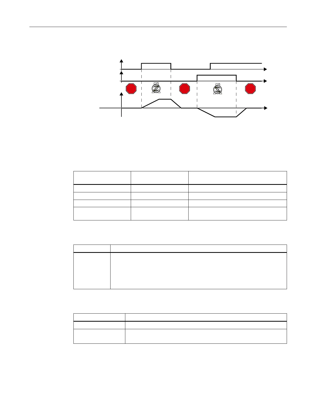
6.4.2 Two-wire control, method 2
&ORFNZLVH
&RXQWHUFORFNZLVH
212))
&RXQWHUFORFNZLVH
212))
&ORFNZLVH
6SHHGVHWSRLQW
&RPPDQGKDVQRHIIHFW
W
W
W
672367236723
Figure 6-7 Two-wire control, method 2
Commands "ON/OFF1 clockwise rotation" and "ON/OFF1 counter-clockwise rotation" switch
on the motor - and simultaneously select a direction of rotation. The inverter only accepts a
new command when the motor is at a standstill.
Table 6-12 Function table
ON/OFF1 clockwise rota‐
tion
ON/OFF1 counter-clock‐
wise rotation
Function
0 0 OFF1: The motor stops.
1 0 ON: Clockwise motor rotation.
0 1 ON: Counter-clockwise motor rotation.
1 1 ON: The motor direction of rotation is defined
by the command that first reaches state "1".
Table 6-13 Select two-wire control, method 2
Parameter Description
p0015 = 12 Macro drive unit
You must carry out quick commissioning in order to set parameter p0015.
Assigning digital inputs DI to the commands:
DI 0: ON/OFF1 clockwise rotation
DI 1: ON/OFF1 counter-clockwise rotation
Table 6-14 Changing the assignment of the digital inputs
Parameter Description
p3330[0 … n] = 722.x BI: 2/3 wire control command 1 (ON/OFF1 clockwise rotation)
p3331[0 … n] = 722.x BI: 2/3 wire control command 2 (ON/OFF1 counter-clockwise rotation)
Example: p3331 = 722.0 ⇒ DI 0: ON/OFF1 counter-clockwise rotation
Advanced commissioning
6.4 Controlling clockwise and counter-clockwise rotation via digital inputs
Converter with the CU230P-2 Control Units
Operating Instructions, 09/2017, FW V4.7 SP9, A5E34257946B AE 213

 Loading...


