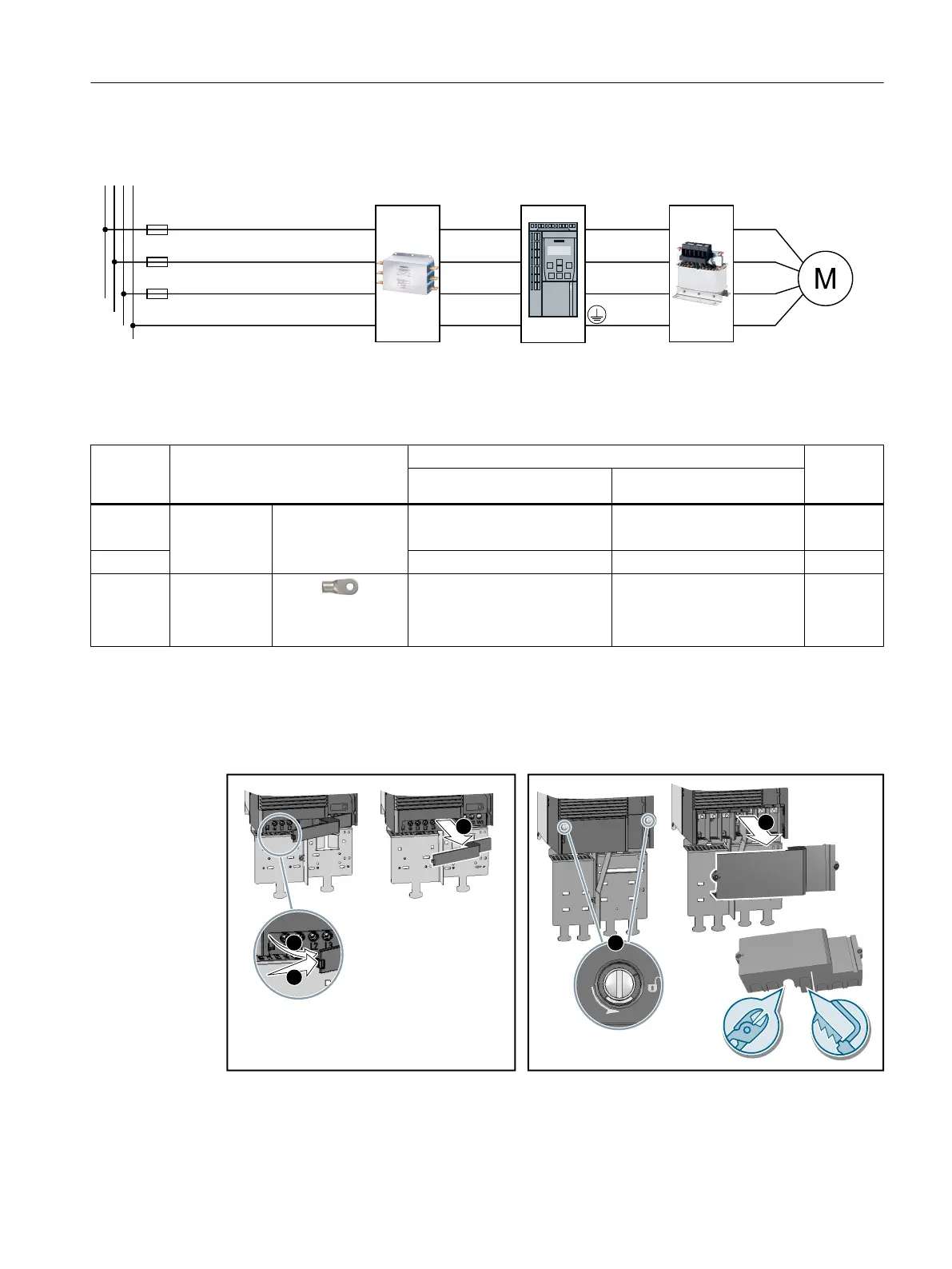
4.4.8 Connecting the inverter with the PM240P-2 Power Module
/LQHILOWHU2XWSXWUHDFWRU,QYHUWHU
8
9
:
3(3(
:
9
8
/
/
/
3(3(
/
/
/
/
/
/
3(
:
9
8
3(
/
/
/
Figure 4-20 PM240P-2 Power Module connection overview
Table 4-28 Connection, cross-section and tightening torque for PM240P-2 Power Modules
Inverters Connection Cross-section, tightening torque Stripped
insulation
length
Metric Imperial
FSD Line supply,
motor
Screw-type termi‐
nal
10 … 35 mm
2
, 2.5 … 4.5 Nm 20 … 10 AWG, 22 lbf in
8 … 2 AWG, 40 lbf in
18 mm
FSE 25 … 70 mm
2
, 8 … 10 Nm 6 … 3/0 AWG, 88.5 lbf in 25 mm
FSF Line supply,
motor
Cable lug accord‐
ing to SN71322
35 … 2 × 120 mm
2
,
22 … 25 Nm
1 … 2 × 4/0 AWG, 210 lbf in --
Connections, frame sizes FSD … FSF
You must remove the covers from the connections in order to connect the line supply and
motor cables to the inverter.
Figure 4-21 Remove the connection covers
Installing
4.4 Connecting the line supply and motor
Converter with the CU230P-2 Control Units
Operating Instructions, 09/2017, FW V4.7 SP9, A5E34257946B AE 97

 Loading...


