4.4.5 Connecting the inverter with the PM230 Power Module IP55
0
3RZHU
0RGXOH
3(
:
9
8/
/
/
3(
:
9
8
3(
/
/
/
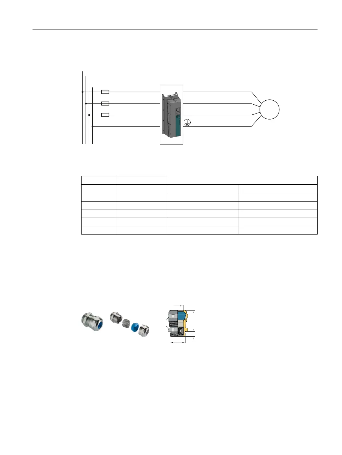
Figure 4-11 PM230 Power Module IP55 connection overview
Table 4-26 Connection types, maximum conductor cross-sections and tightening torques
Inverters Connection Cross-section / tightening torque
FSA Terminal 1 … 2.5 mm
2
/ 0.5 Nm 18 … 14 AWG / 4.4 lbf in
FSB Terminal 2.5 … 6 mm
2
/ 0.6 Nm 14 … 10 AWG, 5.3 lbf in
FSC Terminal 6 …16 mm
2
/ 1.5 Nm 10 … 5 AWG / 13.3 lbf in
FSD Cable lug 10 … 35 mm
2
/ 6 Nm 5 … 2 AWG / 53 lbf in
FSE Cable lug 25 … 50 mm
2
/ 6 Nm 3 … 2 AWG / 53 lbf in
FSF Cable lug 35 … 120 mm
2
/ 13 Nm 2 … 4/0 AWG, 115 lbf in
EMC cable glands
To meet the requirements of degree of protection IP55/UL, type 12, and to fulfill EMC
requirements, adhere to the following:
● Use EMC cable glands for the control cables.
● Make sure that the cable glands match the drill holes in the plate.
Figure 4-12 Example of an EMC cable gland (Blueglobe)
The EMC cable glands are not included in the scope of supply of the inverter. Rubber sleeves
for unused drill holes in the cable cover plate are included in the scope of supply.
Installing
4.4 Connecting the line supply and motor
Converter with the CU230P-2 Control Units
Operating Instructions, 09/2017, FW V4.7 SP9, A5E34257946B AE 89

 Loading...


