Where can you find additional information?
● This manual suffices for assigning a different meaning to the digital inputs.
● The parameter list in the List Manual is sufficient for more complex signal interconnections.
● The function diagrams in the List Manual provide a complete overview of the factory setting
for the signal interconnections and the setting options.
A.4.2 Application example
Shift the control logic into the inverter
It is only permissible that a conveyor system starts when two signals are present
simultaneously. These could be the following signals, for example:
● The oil pump is running (the required pressure level is not reached, however, until after 5
seconds)
● The protective door is closed
To implement this task, you must insert free function blocks between digital input 0 and the
command to switch on the motor (ON/OFF1).
212))
S S
S>@
U
S >PV@
S
S
7
3'(
S>@
U
U
U
S>@
$1'
',
',
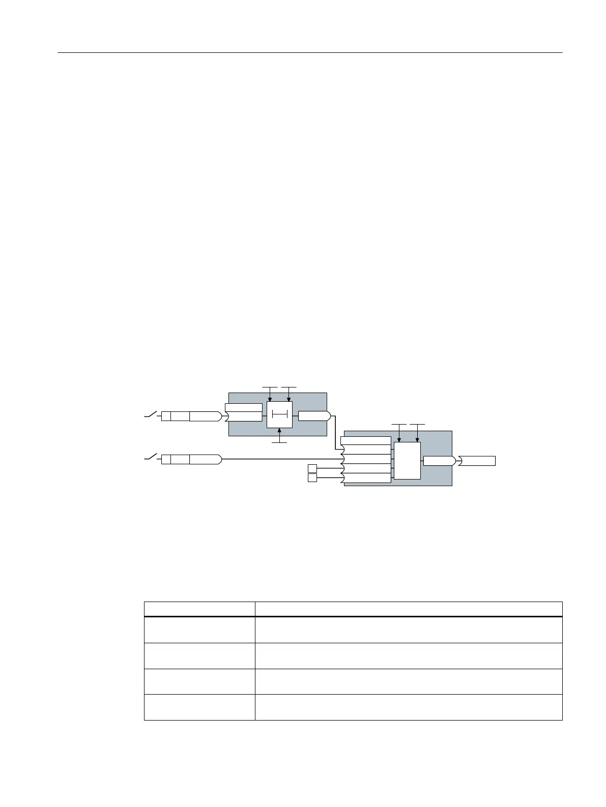
Figure A-7 Signal interconnection for control logic
The signal of digital input 0 (DI 0) is fed through a time block (PDE 0) and is interconnected
with the input of a logic block (AND 0). The signal of digital input 1 (DI 1) is interconnected to
the second input of the logic block. The logic block output issues the ON/OFF1 command to
switch-on the motor.
Setting the control logic
Parameter Description
p20161 = 5 The time block is enabled by assigning to runtime group 5 (time slice of
128 ms)
p20162 = 430 Run sequence of the time block within runtime group 5 (processing before
the AND logic block)
p20032 = 5 The AND logic block is enabled by assigning to runtime group 5 (time slice
of 128 ms)
p20033 = 440 Run sequence of the AND logic block within runtime group 5 (processing
after the time block)
Appendix
A.4 Interconnecting signals in the converter
Converter with the CU230P-2 Control Units
Operating Instructions, 09/2017, FW V4.7 SP9, A5E34257946B AE 535

 Loading...


