Binectors and connectors
Connectors and binectors are used to exchange signals between the individual blocks:
● Connectors are used to interconnect "analog" signals (e.g. MOP output speed)
● Binectors are used to interconnect digital signals (e.g. "Enable MOP up" command)
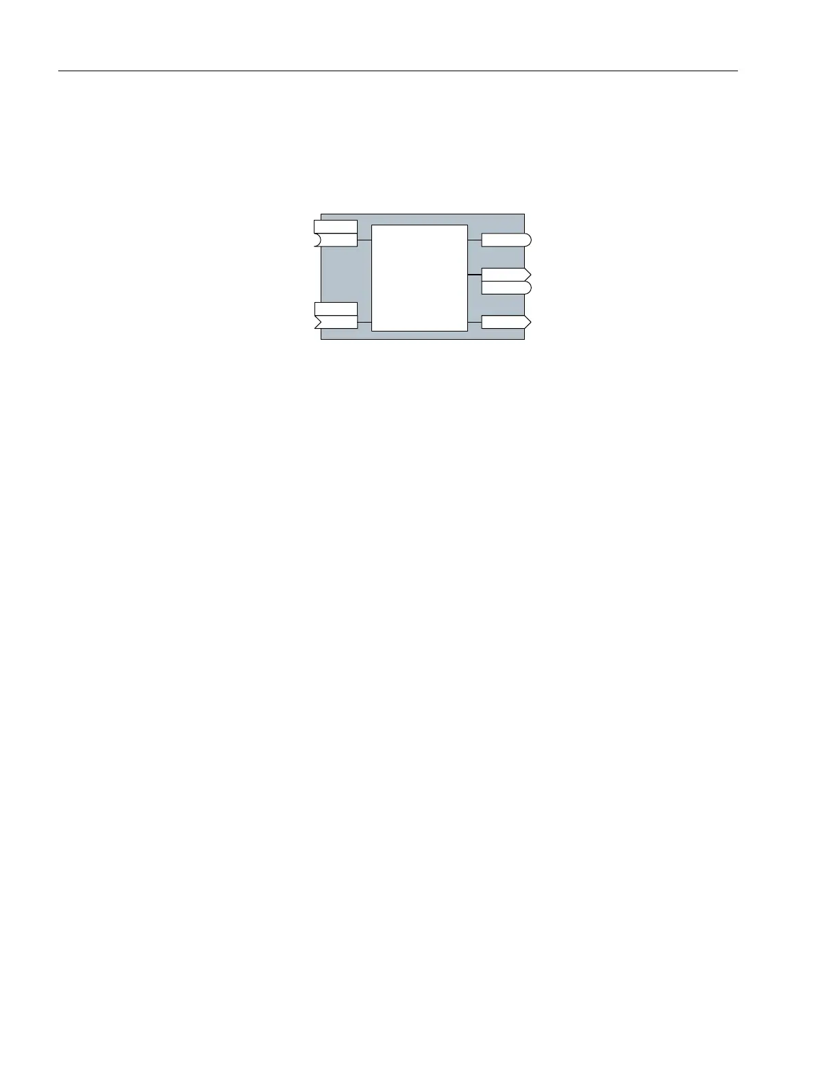
%,&2EORFN
%LQHFWRULQSXW
%LQHFWRURXWSXW
%LQHFWRUFRQQHFWRURXWSXW
&RQQHFWRURXWSXW
&RQQHFWRULQSXW
S[[[[
U[[[[
U[[[[
U[[[[
U[[[[
S[[[[
%,
&2
%2
&2%2
&,
Figure A-6 Symbols for binector and connector inputs and outputs
Binector/connector outputs (CO/BO) are parameters that combine more than one binector
output in a single word (e.g. r0052 CO/BO: status word 1). Each bit in the word represents a
digital (binary) signal. This summary reduces the number of parameters and simplifies
parameter assignment.
Binector or connector outputs (CO, BO or CO/BO) can be used more than once.
Interconnecting signals
When must you interconnect signals in the inverter?
If you change the signal interconnection in the inverter, you can adapt the inverter to a wide
range of requirements. This does not necessarily have to involve highly complex functions.
Example 1: Assign a different function to a digital input.
Example 2: Switch the speed setpoint from the fixed speed to the analog input.
Principle when connecting BICO blocks using BICO technology
When interconnecting the signal, the following principle applies: Where does the signal come
from?
An interconnection between two BICO blocks consists of a connector or a binector and a BICO
parameter. The input of a block must be assigned the output of a different block: In the BICO
parameters, enter the parameter numbers of the connector/binector that should supply its
output signal to the BICO parameter.
How much care is required when you change the signal interconnection?
Note which changes you make. A subsequent analysis of the set signal interconnections is
possible only by evaluating the parameter list.
We recommend that you use the STARTER and Startdrive commissioning tools for setting the
signal interconnections.
Appendix
A.4 Interconnecting signals in the converter
Converter with the CU230P-2 Control Units
534 Operating Instructions, 09/2017, FW V4.7 SP9, A5E34257946B AE

 Loading...


