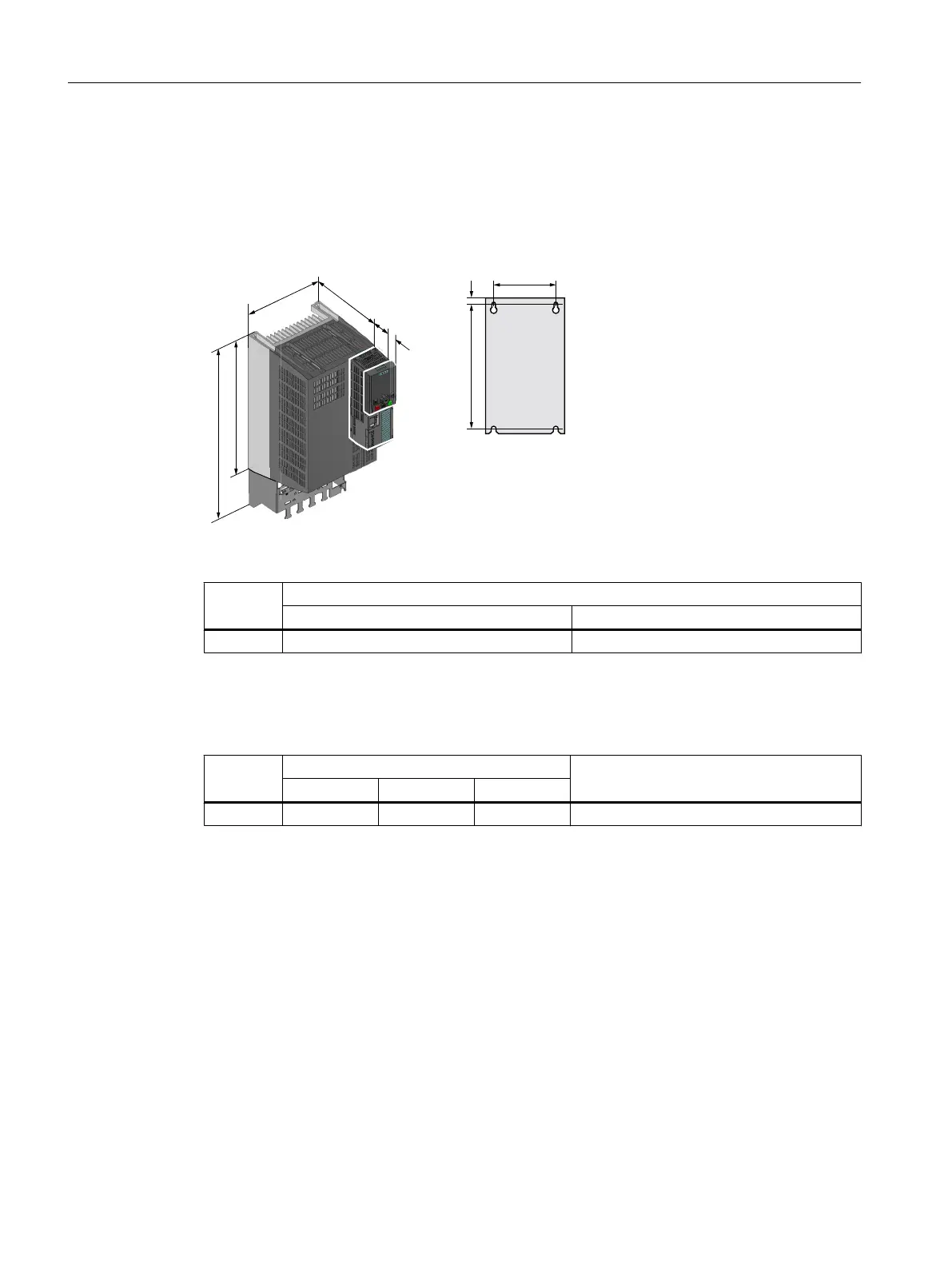
4.3.7 Dimensioned drawings, drilling dimensions for the PM250 Power Module
The following dimension drawings and drilling patterns are not to scale.
Frame size FSC
Table 4-16 Dimensions depend on the operator panel (OP) that is inserted
Frame
size
Mounting depth in the cabinet with Control Unit (CU) [mm]
without OP with OP
1)
FSC 224 235
1)
BOP-2, IOP-2 or blanking cover
Table 4-17 Cooling air clearances and fastening
Frame
size
Cooling air clearances [mm]
1)
Fixing/torque [Nm]
Top Bottom Front
FSC 125 125 65 4 x M5 / 3
1)
You can mount the Power Modules without any lateral cooling air clearance. For tolerance reasons,
we recommend a lateral clearance of approx. 1 mm.
Installing
4.3 Installing Power Modules
Converter with the CU230P-2 Control Units
76 Operating Instructions, 09/2017, FW V4.7 SP9, A5E34257946B AE

 Loading...


