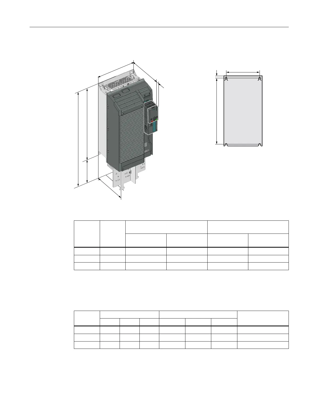
Frame sizes FSD … FSF
+HLJKWZLWKRXWVKLHOGSODWH
+HLJKWZLWKVKLHOGSODWH
'HSWK
6KLHOG
SODWH
:LGWK
'HSWKZLWK&8
23
K
E
F
Table 4-14 Dimensions depend on the operator panel (OP) that is inserted
1)
Frame
size
Width
[mm]
Height [mm] Mounting depth in the cabinet with
Control Unit (CU) [mm]
2)
without shield
plate
with shield plate without OP with OP
1)
FSD 275 517 650 253 264
FSE 354 615 722 253 264
FSF 384 754 1021 373 384
1)
BOP-2, IOP-2 or blanking cover
2)
Power Module depth without Control Unit: FSD, FSE 237 mm, FSF 357 mm
Table 4-15 Drilling dimensions, cooling clearances and fixing
Frame
size
Drilling dimensions [mm] Cooling air clearances [mm]
1)
Fixing/torque [Nm]
h b c Top Bottom Front
FSD 430 170 7 300 350 100 4 x M5 / 6.0
FSE 509 230 8.5 300 350 100 4 x M6 / 10
FSF 680 270 13 300 350 100 4 x M8 / 25
1)
The Power Module is designed for mounting without any lateral cooling air clearance. For tolerance
reasons, we recommend a lateral clearance of approx. 1 mm.
Installing
4.3 Installing Power Modules
Converter with the CU230P-2 Control Units
Operating Instructions, 09/2017, FW V4.7 SP9, A5E34257946B AE 75

 Loading...


