Advanced commissioning
6
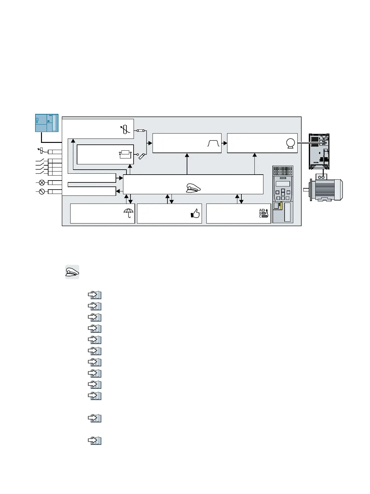
6.1 Overview of the inverter functions
0
'ULYHFRQWURO
0RWRUFRQWURO
&RPPDQGV
6HWSRLQWV
6WDWXV
3URWHFWLRQ$YDLODELOLW\
(QHUJ\VDYLQJ
6HWSRLQWSURFHV
VLQJ
7HFKQRORJ\
FRQWUROOHU
3RZHU
0RGXOH
&RQWURO8QLW
3,'
Figure 6-1 Overview of inverter functions
Drive control
The inverter receives its commands from the higher-level control via the terminal strip or the
fieldbus interface of the Control Unit. The drive control defines how the inverter responds to
the commands.
Sequence control when switching the motor on and off (Page 195)
Adapt the default setting of the terminal strip (Page 197)
Controlling clockwise and counter-clockwise rotation via digital inputs (Page 210)
Drive control via PROFIBUS or PROFINET (Page 217)
Drive control via USS (Page 234)
Drive control via Modbus RTU (Page 237)
Drive control via Ethernet/IP (Page 240)
Drive control via BACnet MS/TP (Page 241)
Drive control via P1 (Page 244)
Jogging (Page 249)
The inverter can switch between different settings of the drive control.
Switching over the drive control (command data set) (Page 250)
The free function blocks permit configurable signal processing within the inverter.
Free function blocks (Page 252)
Converter with the CU230P-2 Control Units
Operating Instructions, 09/2017, FW V4.7 SP9, A5E34257946B AE 191

 Loading...


