4.5.2 Overview of the interfaces
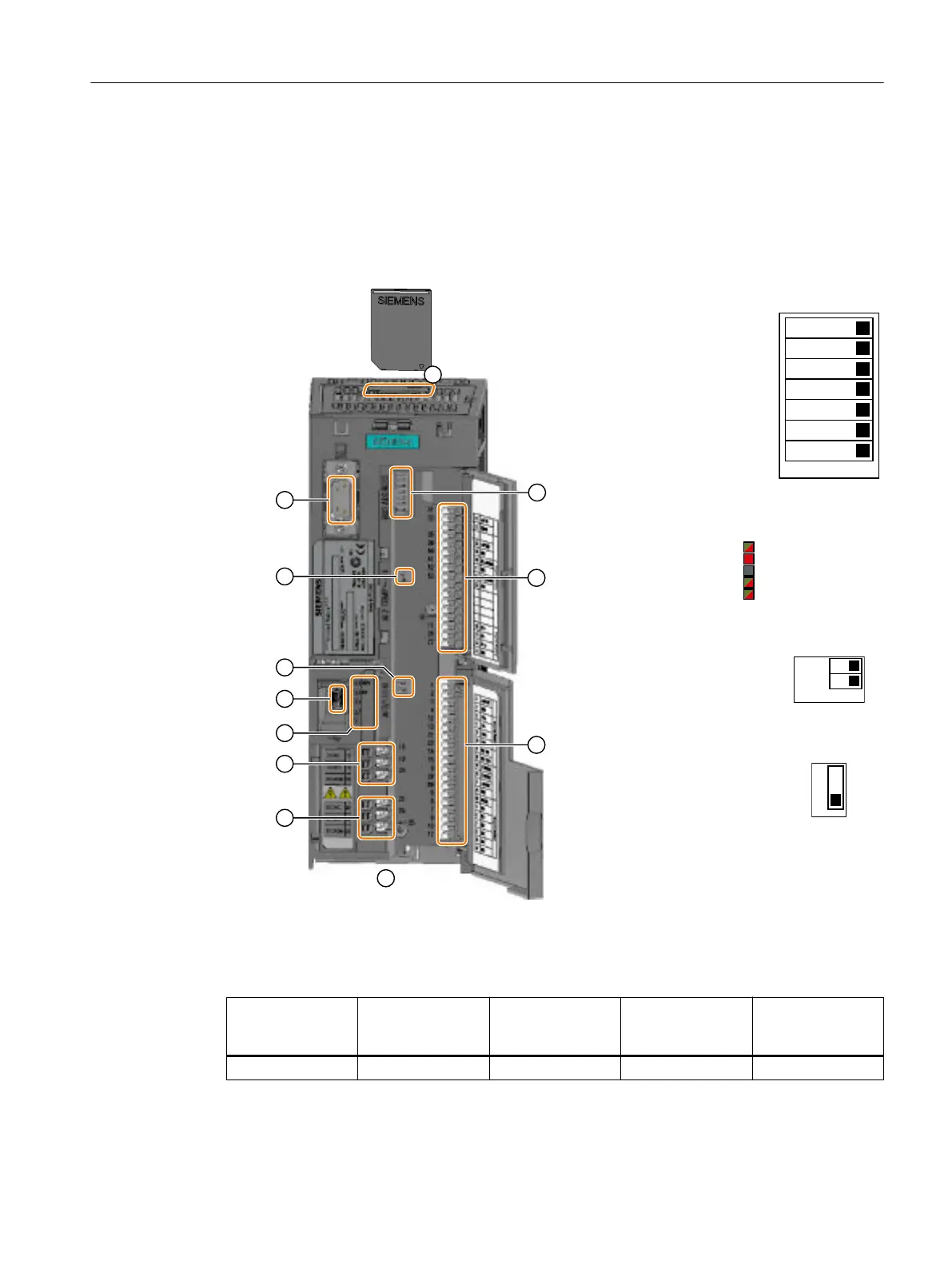
Interfaces at the front of the Control Unit
To access the interfaces at the front of the Control Unit, you must lift the Operator Panel (if
one is being used) and open the front doors.
;
;
;
;
;
;
;
;
;
① Memory card slot
② Selecting the field‐
bus address:
● CU230P-2 DP
● CU230P-2
HVAC
● CU230P-2 BT
2II2Q
%LW
%LW
%LW
%LW
%LW
%LW
%LW
③ Terminal strips
④ Fieldbus interfaces at the lower side
⑤ Status LED
5'<
%)
/1.352),1(7
/1.352),1(7
⑥ USB interface for connection to a
PC
⑦ Switch for AI 0 and
AI 1 (U/I)
● I 0/4 mA … 20 mA
● U -10/0 V … 10 V
⑧ Switch for AI 2
Current or tempera‐
ture input
⑨ Connection to the operator panel
Table 4-31 Number of inputs and outputs
Digital inputs DI Digital outputs DO Analog inputs AI Analog outputs AO Input for motor
temperature sen‐
sor
6 3 4 2 1
Installing
4.5 Connecting the interfaces for the inverter control
Converter with the CU230P-2 Control Units
Operating Instructions, 09/2017, FW V4.7 SP9, A5E34257946B AE 109

 Loading...


