10.5 Technical data, PM330 Power Module
Permissible inverter overload
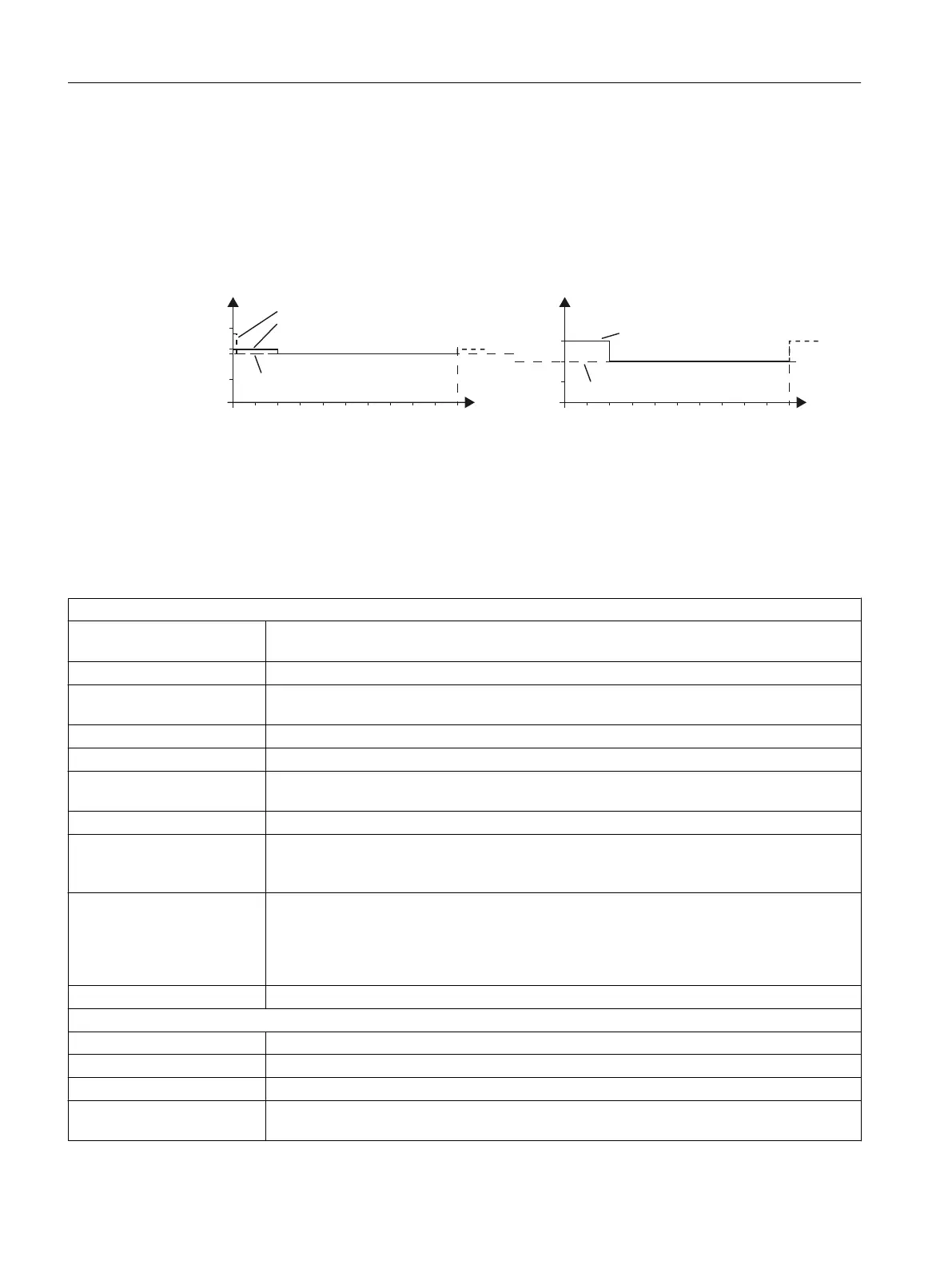
The inverters have different load capabilities, "High Overload" and "Low Overload", depending
on the expected.
RYHUORDGIRUVHFRQGV
RYHUORDGIRUVHFRQGV
RYHUORDGIRUVHFRQGV
%DVHORDGIRUVHFRQGV
%DVHORDGIRUVHFRQGV
/2EDVHORDG
+2EDVHORDG
W>V@
W>V@
Figure 10-4 Load cycles, Low Overload" and "High Overload"
10.5.1 General technical data, PM330
Table 10-29 General technical data
Electrical data
Line system configurations Grounded TN/TT systems or ungrounded IT systems (a grounded phase conductor is not
permissible in 690 V line supplies)
Line requirement A line reactor (2% u
k
) must be connected in series
Line voltage 380 V (-10 %) ... 480 V (+10 %)
500 V (-10 %) ... 690 V (+10 %)
Line frequency 47 … 63 Hz
Output frequency 0 ... 100 Hz
Displacement factor cos φ
power factor λ
0.96
0.75 ... 0.93 (with line reactor u
k
= 2%)
Converter efficiency > 98%
Short-circuit current rating ac‐
cording to IEC, in conjunction
with the specified fuses
160 ... 630 kW: 100 kA
Short-circuit current rating ac‐
cording to UL61800-5-1 (up
to 480 V AC or 600 V AC), in
conjunction with the specified
fuses
160 ... 630 kW: 100 kA
Can be used on line supplies that cannot supply more than 100 kA symmetrically at a maxi‐
mum voltage of 480 V AC or 600 V AC when they are protected with the semiconductor fuses
specified in Chapter "Technical Data" of this manual.
Overvoltage category III according to EN 61800-5-1
Mechanical data
Degree of protection IP20
Protection class according to EN 61800-5-1: Class I (with protective conductor system) and Class III (PELV)
Cooling method Forced air cooling AF according to EN 60146
Sound pressure level L
PA
(1
ma)
≤ 74 dB(A)
1)
Technical data
10.5 Technical data, PM330 Power Module
Converter with the CU230P-2 Control Units
464 Operating Instructions, 09/2017, FW V4.7 SP9, A5E34257946B AE

 Loading...


