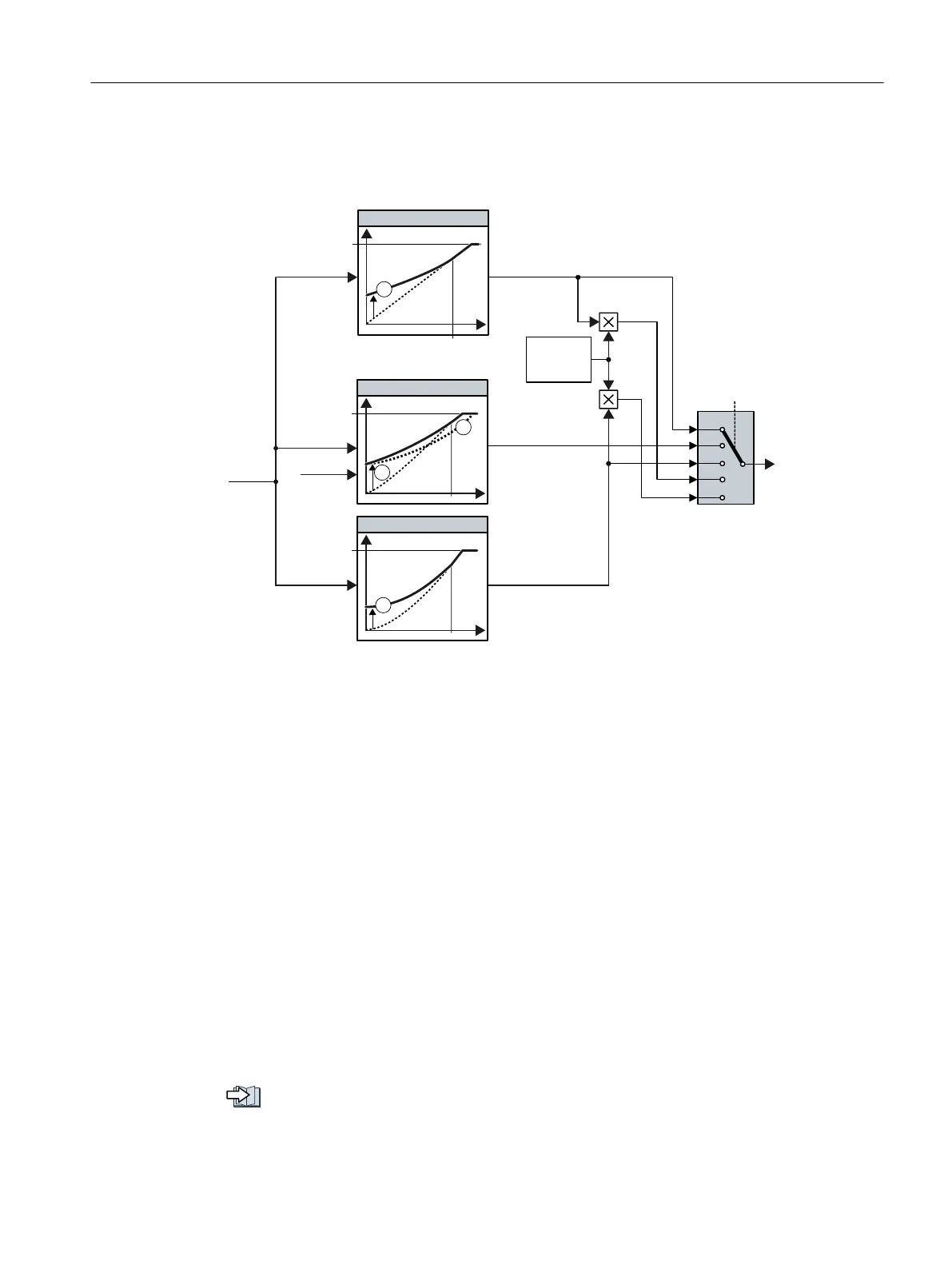
6.24.2.1 Characteristics of U/f control
The inverter has different V/f characteristics.
1
1
2
1
8
VHW
6HOHFWLRQRIWKH
FKDUDFWHULVWLF
(&2
PRGH
I
VHW
,
TBVHW
0D[LPXPRXWSXW
YROWDJH
5DWHGPRWRUIUHTXHQF\
/LQHDU
3DUDEROLF
)&&
S
S
U
S
U
S
U
① The voltage boost of the characteristic optimizes motor starting
② With flux current control (FCC), the inverter compensates the voltage drop across the stator resist‐
ance of the motor
Figure 6-41 V/f characteristics of the inverter
The inverter increases its output voltage up to the maximum output voltage. The line voltage
defines the maximum inverter output voltage.
If the inverter has reached its maximum output voltage, then it can only increase its output
frequency. From this point onwards, the motor is operated in field weakening; this means that
the available torque linearly decreases with increasing speed.
The value of the output voltage at the rated motor frequency also depends on the following
variables:
● Ratio between the inverter size and the motor size
● Line voltage
● Line impedance
● Actual motor torque
The maximum possible output voltage as a function of the input voltage is provided in the
technical data.
Technical data (Page 435)
Advanced commissioning
6.24 Motor control
Converter with the CU230P-2 Control Units
Operating Instructions, 09/2017, FW V4.7 SP9, A5E34257946B AE 299

 Loading...


