6.23 Time switch (DTC)
The "time switch" (DTC) function, along with the real-time clock in the inverter, offers the option
of controlling when signals are switched on and off.
Examples:
● Switching temperature control from day to night mode.
● Switching a process control from weekday to weekend.
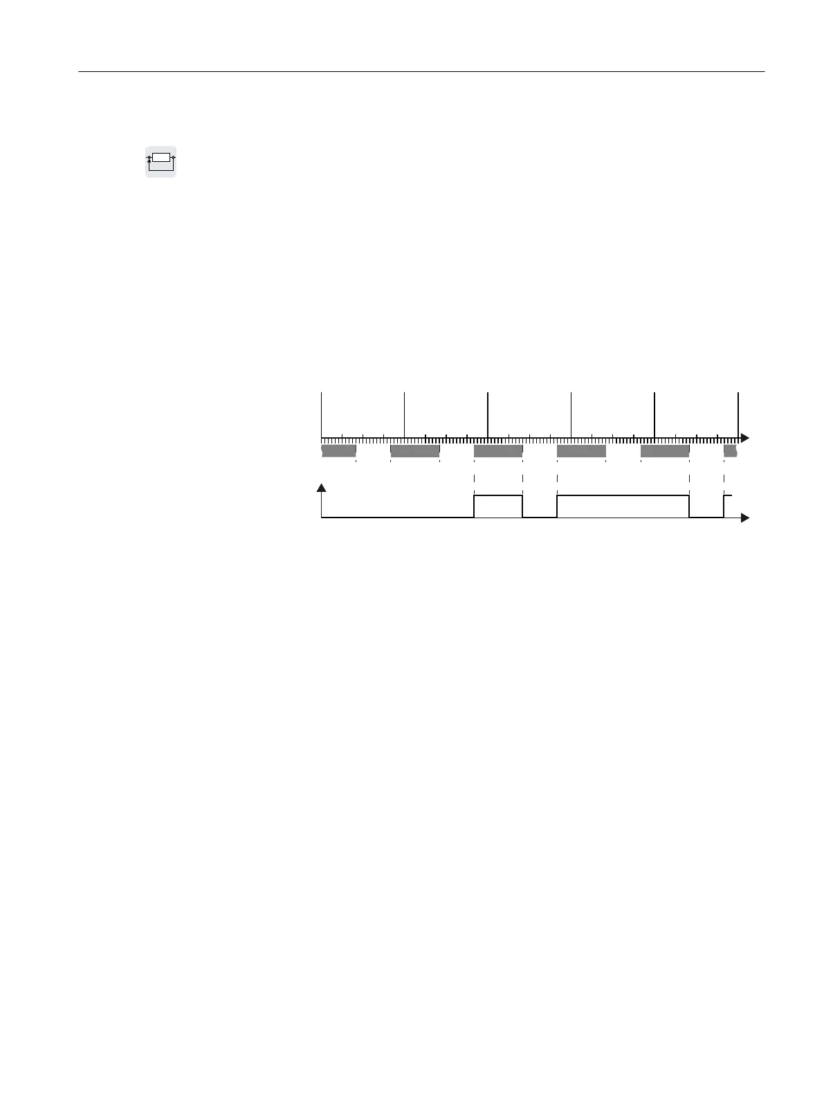
Principle of operation of the time switch (DTC)
The inverter has three independently adjustable time switches. The time switch output can be
interconnected with every binector input of your inverter, e.g. with a digital output or a
technology controller's enable signal.
W
0RQGD\7XHVGD\:HGQHVGD\7KXUVGD\
W
GHDFWLYDWHGDFWLYDWHGDFWLYDWHGDFWLYDWHGGHDFWLYDWHG
)ULGD\
21
6LJQDODWWKHRXWSXW
21212121
'7&ZHHNGD\
DFWLYDWLRQ
'7&VZLWFKLQJWLPHV
57&
SSU
Figure 6-38 Example of the response of the time switch.
Settings for the example with DTC1
● Enable parameterization of the DTC: p8409 = 0.
As long as the parameterization of the DTC is enabled, the inverter holds the output of all
three DTC (r84x3, x = 1, 2, 3; r84x3.0 normal, r84x3.1 inverted status message) at LOW.
● Activate/deactivate the weekday
- p8410[0] = 0 Monday
- p8410[1] = 1 Tuesday
- p8410[2] = 1 Wednesday
- p8410[3] = 0 Thursday
- p8410[4] = 1 Friday
- p8410[5] = 1 Saturday
- p8410[6] = 0 Sunday
● Setting switching times:
– ON: p8411[0] = 20 (hh), p8411[1] = 0 (MM)
– OFF: p8412[0] = 10 (hh), p4812[1] = 0 (MM)
● Enable the setting: p8409 = 1.
The inverter re-enables the DTC output.
Additional information is provided in the parameter list of the List Manual.
Advanced commissioning
6.23 Time switch (DTC)
Converter with the CU230P-2 Control Units
Operating Instructions, 09/2017, FW V4.7 SP9, A5E34257946B AE 295

 Loading...


