3.1 Identifying the converter
Main components of the inverter
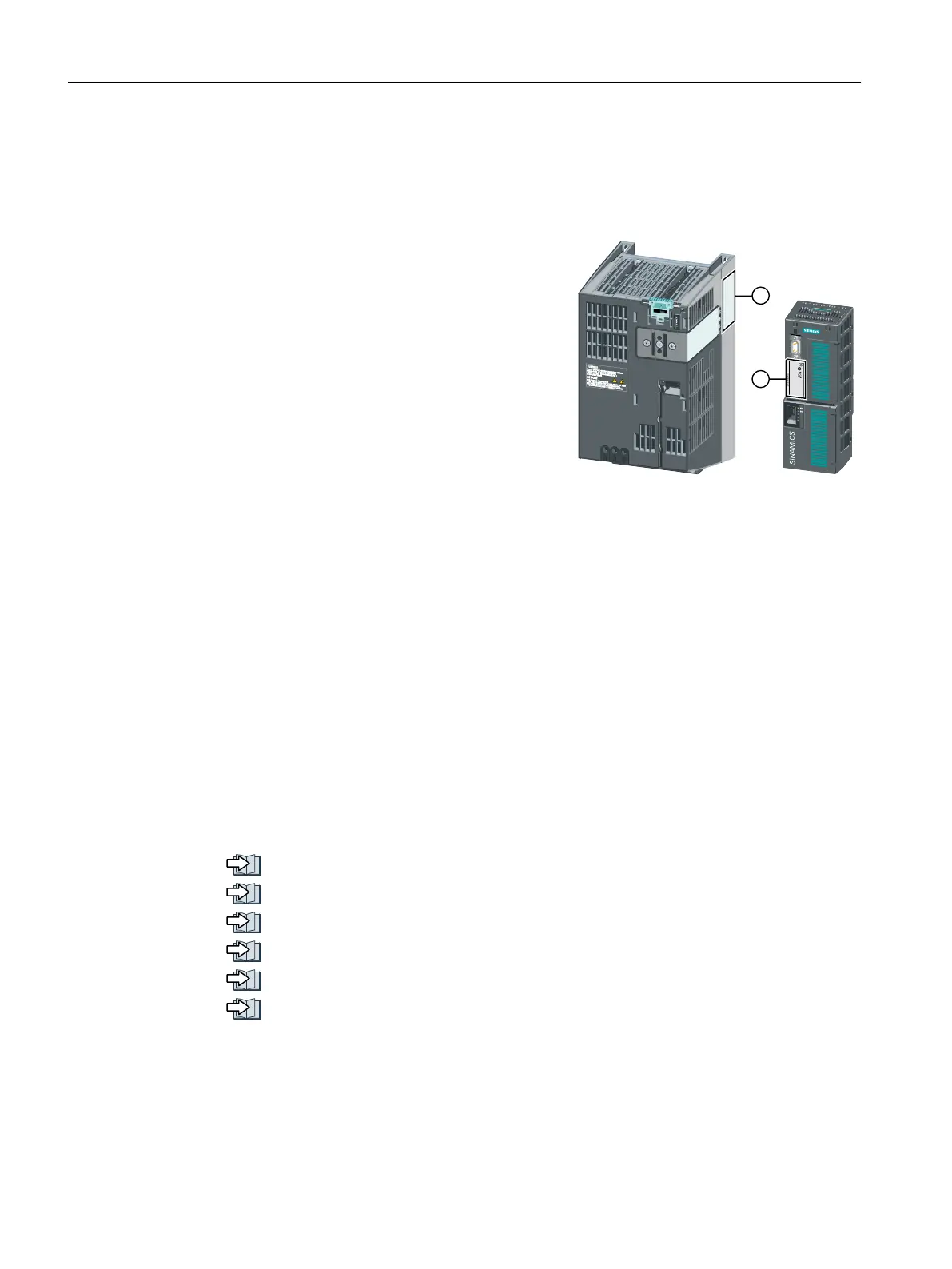
Each SINAMICS G120 inverter comprises a Control
Unit and a Power Module.
● The Control Unit controls and monitors the
connected motor.
● The Power Module provides the connections for
line supply and motor.
&RQWURO8QLW
3RZHU0RGXOH
The following data is provided on the Power Module type plate (①):
● Designation, e.g. PM240-2 Power Module
● Technical specifications: voltage and current
● Article number, e.g. 6SL3210-1PE21-1UL0
● Version, e.g. A02
The following data can be found on the Control Unit type plate (②):
● Designation, e.g. Control Unit CU240E-2 DP-F
● Article number, e.g. 6SL3244-0BB13-1PA0
● Version, e.g. A02 (hardware), 4.7 (firmware)
Further inverter components
The following components are available so that you can adapt the inverter to different
applications and ambient conditions:
● Line filter (Page 42)
● Line reactor (Page 44)
● Output reactor (Page 46)
● Sine-wave filter (Page 51)
● dv/dt filter (Page 52)
● Braking Module and braking resistor (Page 53)
Description
3.1 Identifying the converter
Converter with the CU230P-2 Control Units
30 Operating Instructions, 09/2017, FW V4.7 SP9, A5E34257946B AE

 Loading...


