6.3.2 Digital outputs
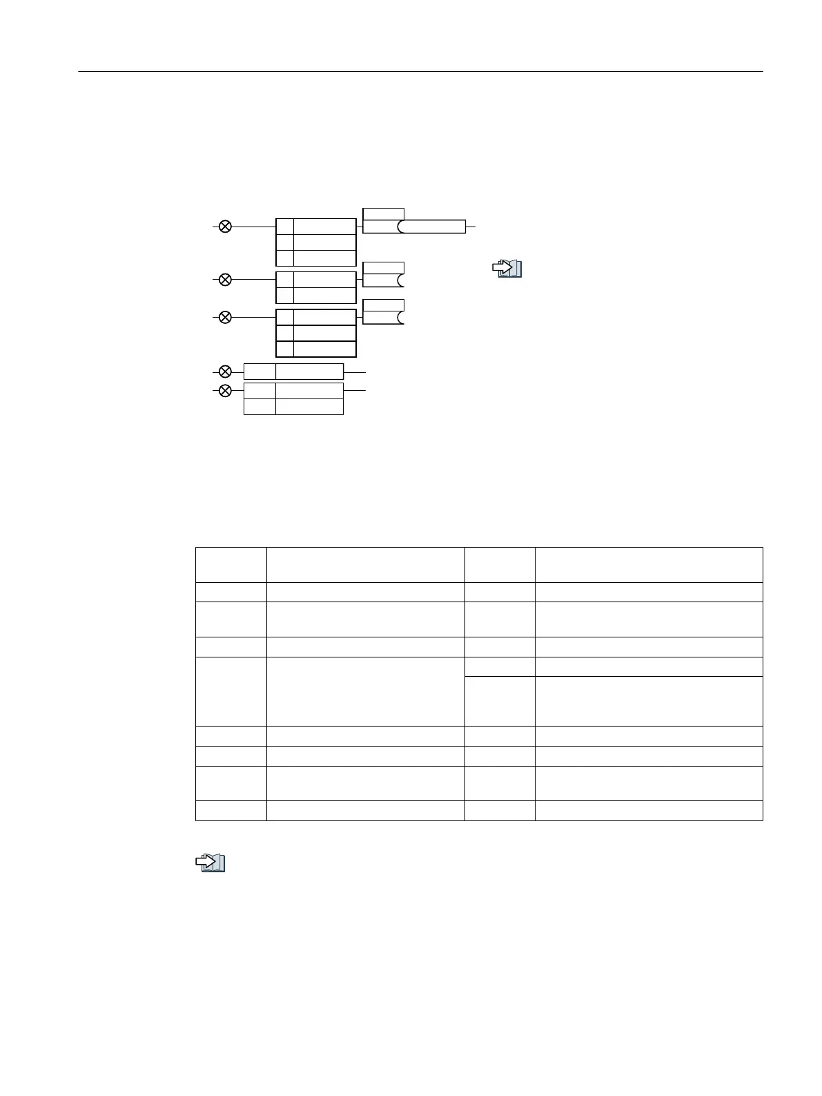
Changing the function of a digital output
'21&
'212
'2&20
'212
'2&20
%2U\\[[Q
S
S
'21&
'212
'2&20
S
'2
;
'21&
'2&20
;
;
U
U
To change the function of a digital output,
you must interconnect the digital output with
a binector output of your choice.
Interconnecting signals in the convert‐
er (Page 533)
Binector outputs are marked with "BO" in the
parameter list of the List Manual.
1)
When using the PM330 Power Module, the inverter has 2 additional digital outputs. The
function of the two additional digital outputs is fixed and cannot be modified:
● DO 0 (X9.8): Inverter DC link is charged
● DO 1 (X9.11, X9.12): Close main contactor
Table 6-4 Frequently used binector outputs (BO) of the inverter
0 Deactivating digital output r0052.08 0 signal: Deviation, setpoint/actual
speed
r0052.00 1 signal: Ready for switching on r0052.09 1 signal: Control requested
r0052.01 1 signal: Ready for operation r0052.10 1 signal: Maximum speed (p1082)
reached
r0052.02 1 signal: Operation enabled r0052.11 0 signal: I, M, P limit reached
r0052.03 1 signal: Fault active
The inverter inverts signal
r0052.03 if it is interconnected to
a digital output.
r0052.13 0 signal: Alarm overtemperature motor
r0052.14 1 signal: Motor CW rotation
r0052.04 0 signal: OFF2 active r0052.15 0 signal: Alarm inverter overload
r0052.05 0 signal: OFF3 active r0053.00 1 signal: DC braking active
r0052.06 1 signal: Closing lockout active r0053.02 1 signal: Speed > minimum speed
(p1080)
r0052.07 1 signal: Alarm active r0053.06 1 signal: Speed ≥ setpoint speed (r1119)
The complete list of binector outputs is provided in the List Manual.
Overview of the manuals (Page 537)
Advanced commissioning
6.3 Adapt the default setting of the terminal strip
Converter with the CU230P-2 Control Units
Operating Instructions, 09/2017, FW V4.7 SP9, A5E34257946B AE 201

 Loading...


