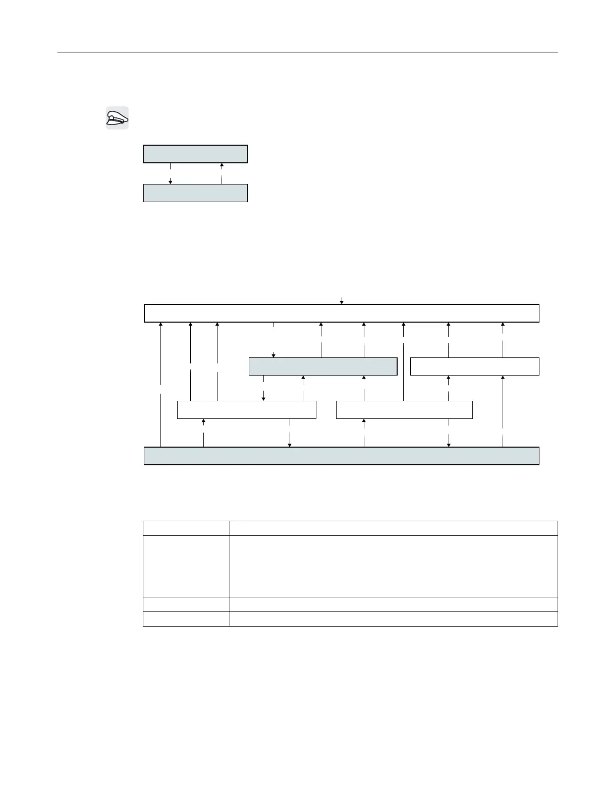
6.2 Sequence control when switching the motor on and off
After switching the supply voltage on, the inverter normally goes into the "ready to start" state.
In this state, the inverter waits for the command to switch on the motor:
5HDG\WRVZLWFKRQ
2SHUDWLRQ
2))21
The inverter switches on the motor with the ON command. The in‐
verter changes to the "Operation" state.
The inverter brakes the motor to standstill after the OFF1 command.
The inverter switches off the motor once standstill has been reached.
The inverter is again "ready to start".
Inverter states and commands for switching the motor on and off
In addition to ON/OFF1, "Ready to switch on" and "Ready", there are no additional inverter
states and commands to switch on and switch off the motor:
6ZLWFKRQLQKLELW
4XLFNVWRS
1RUPDOVWRS
5HDG\WRVWDUW
5HDG\
2SHUDWLRQ
(QDEOHRSHUDWLRQ'LVDEOHRSHUDWLRQ
0RWRUVWDWLRQDU\
0RWRUVWDWLRQDU\
6ZLWFKRQWKHSRZHUVXSSO\RIWKHLQYHUWHU
DQGQRW
DQGQRW
21
2))
2))
2))2))
2))2))
2))
2))
2))
2))
2))
2))
21
2))
2))
6
6
6
6
6
6
Figure 6-2 Internal sequence control of the inverter when the motor is switched on and off
Table 6-1 Commands for switching the motor on and off
OFF2 The inverter switches off the motor immediately without first braking it.
OFF3 The inverter changes from the "Operation" state to the "Quick stop" state. During
"Quick stop", the inverter brakes the motor with the OFF3 ramp-down time. The
inverter switches off the motor once standstill has been reached.
The command is frequently used for exceptional operating situations where it is
necessary to brake the motor very fast, e.g. for collision protection.
Disable operation The inverter switches the motor OFF.
Enable operation The inverter switches the motor ON.
Advanced commissioning
6.2 Sequence control when switching the motor on and off
Converter with the CU230P-2 Control Units
Operating Instructions, 09/2017, FW V4.7 SP9, A5E34257946B AE 195

 Loading...


