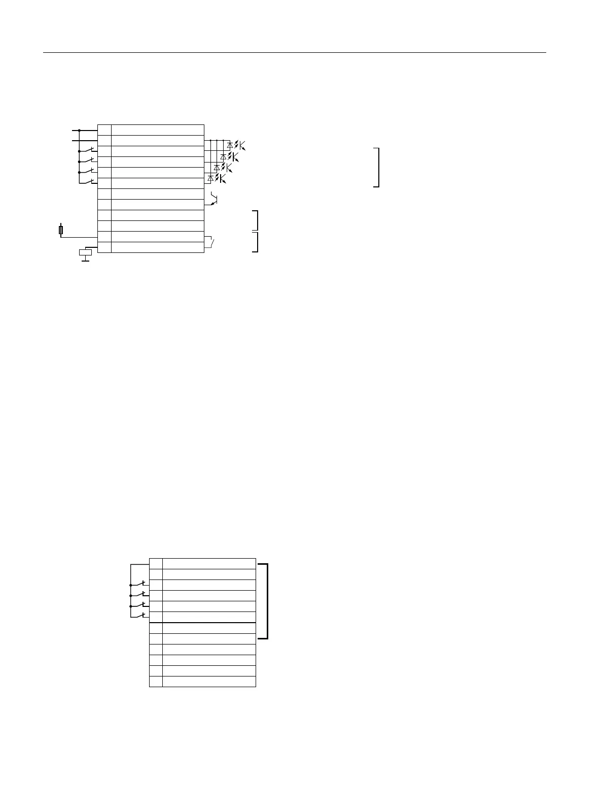
External 24 V supply of the terminal strip X9
([WHUQDOVXSSO\99PD[$
5HIHUHQFHIRUWHUPLQDOVDQG
5HIHUHQFHIRUWHUPLQDOVDQG
1RWFRQQHFWHG
0DLQFRQWDFWRUFRQWURO9$&FRV˳ LQGPD[
$
0HVVDJH8
'&OLQN
LVORDGHG9'&PD[P$
([WHUQDODODUP
([WHUQDOIDXOW
2))
2))
'LJLWDOLQSXWV
ORZ9KLJK!9PD[9
LQSXWFXUUHQWP$DW9
;
3
0
([WHUQDO$OHUW
([WHUQDOIDXOW
6WRS
6WRS
0
'&/LQN&KDUJHG
1&
1&
$FWLYDWLRQ/LQH&RQWDFWRU
$FWLYDWLRQ/LQH&RQWDFWRU
9
H[W
$&9
*1'
H[W
Connection cross-section: 0.2 mm² … 2.5 mm², tightening torque: 0.5 Nm (5 lb.in)
Use insulated end sleeves according to DIN 46228-4.
Terminals Remark
3 … 6 The function of the digital inputs is shown in the factory setting.
You can change the function of the digital inputs subsequently.
The digital inputs are low-active in the factory setting. If you do not use one of the digital inputs, you must
connect the digital input with 24 V.
8, 11, 12 The function of the digital outputs cannot be changed.
8 The digital output signals a fully charged DC link of the inverter. A charged DC link is the prerequisite for the
"operation" inverter state.
11, 12 A device to protect against overload and short-circuit is required for the power supply to the line contactor
control, e.g. a 4 A / 250 V fuse.
Connect the excitation coil of the line contactor to a surge suppressor, e.g. an RC element.
Figure 4-32 Terminal strip X9 on the PM330 power module with an external 24 V supply
Internal 24 V supply of the terminal strip X9
As from function version 04 (FS04) of the power module, the terminal strip X9 has an internal
24 V supply. The load of the internal 24 V supply is however limited.
6XPPDWLRQRIWKHORDGRQ;DQG;PD[bP$
;
3
0
([WHUQDO$OHUW
([WHUQDOIDXOW
6WRS
6WRS
0
'&/LQN&KDUJHG
1&
1&
$FWLYDWLRQ/LQH&RQWDFWRU
$FWLYDWLRQ/LQH&RQWDFWRU
Figure 4-33 Terminal strip X9 on the PM330 power module with an internal 24 V supply
Installing
4.5 Connecting the interfaces for the inverter control
Converter with the CU230P-2 Control Units
132 Operating Instructions, 09/2017, FW V4.7 SP9, A5E34257946B AE

 Loading...


