Select the default setting for the interfaces of the inverter that is suitable for your application.
Default setting of the interfaces (Page 115)
CAUTION
Material damage caused by unexpected acceleration of the motor
Depending on the Power Module, the inverter sets the minimum frequency p1080 to 20% of
the maximum frequency. Also for a setpoint = 0, for p1080 > 0, after the motor is switched
on it accelerates to the minimum frequency. An unexpected acceleration of the motor can
cause material damage.
● If the application requires a minimum frequency = 0, then set p1080 = 0.
Figure 5-11 Minimum/maximum frequency of the motor
Scaling of analog input 0
I
6HWSRLQW
3
3
W
I
PD[
3
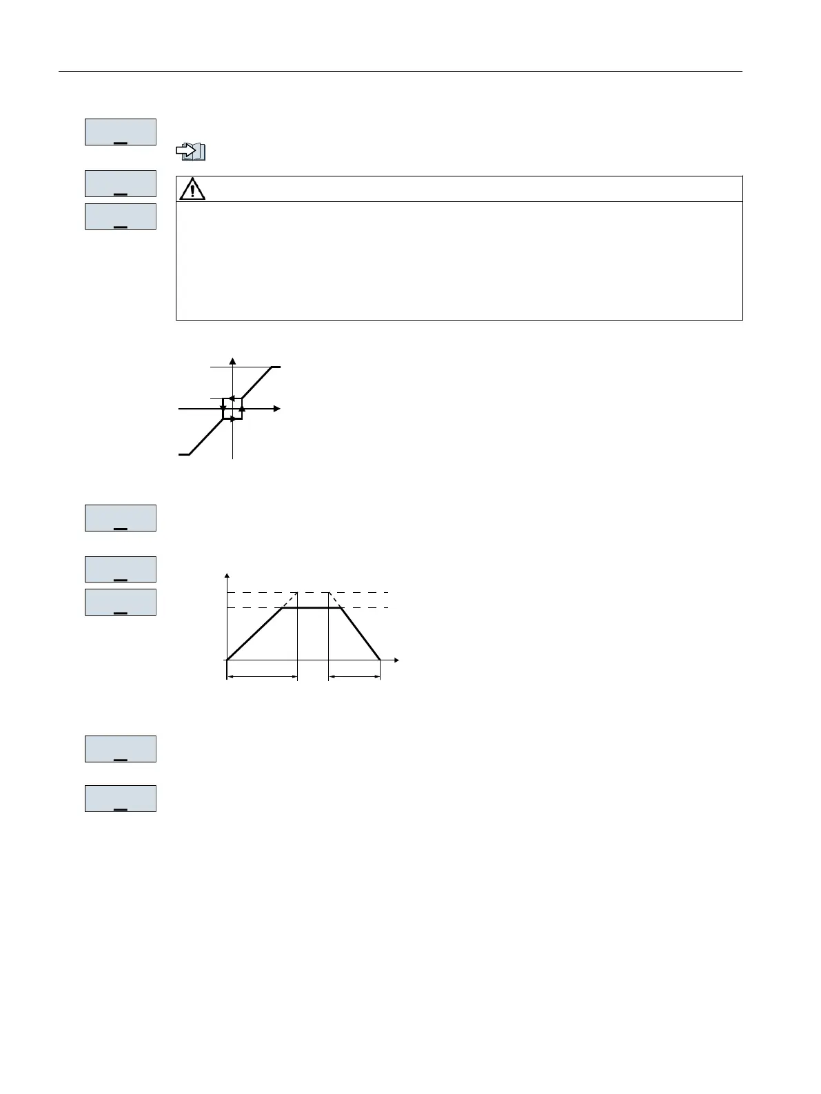
Figure 5-12 Ramp-up and ramp-down time of the motor
Ramp-down time for the OFF3 command
Motor data identification: Select the method which the inverter uses to measure the data of
the connected motor:
● OFF: No motor data identification
● STIL ROT: Recommended setting: Measure the motor data at standstill and with the motor
rotating.
The inverter switches off the motor after the motor data identification has been completed.
● STILL: Default setting: Measure the motor data at standstill.
The inverter switches off the motor after the motor data identification has been completed.
Select this setting if the motor cannot freely rotate, e.g. for a mechanically limited traversing
range.
3
5$0383
3
5$03':1
Commissioning
5.4 Quick commissioning using the BOP-2 operator panel
Converter with the CU230P-2 Control Units
166 Operating Instructions, 09/2017, FW V4.7 SP9, A5E34257946B AE

 Loading...


