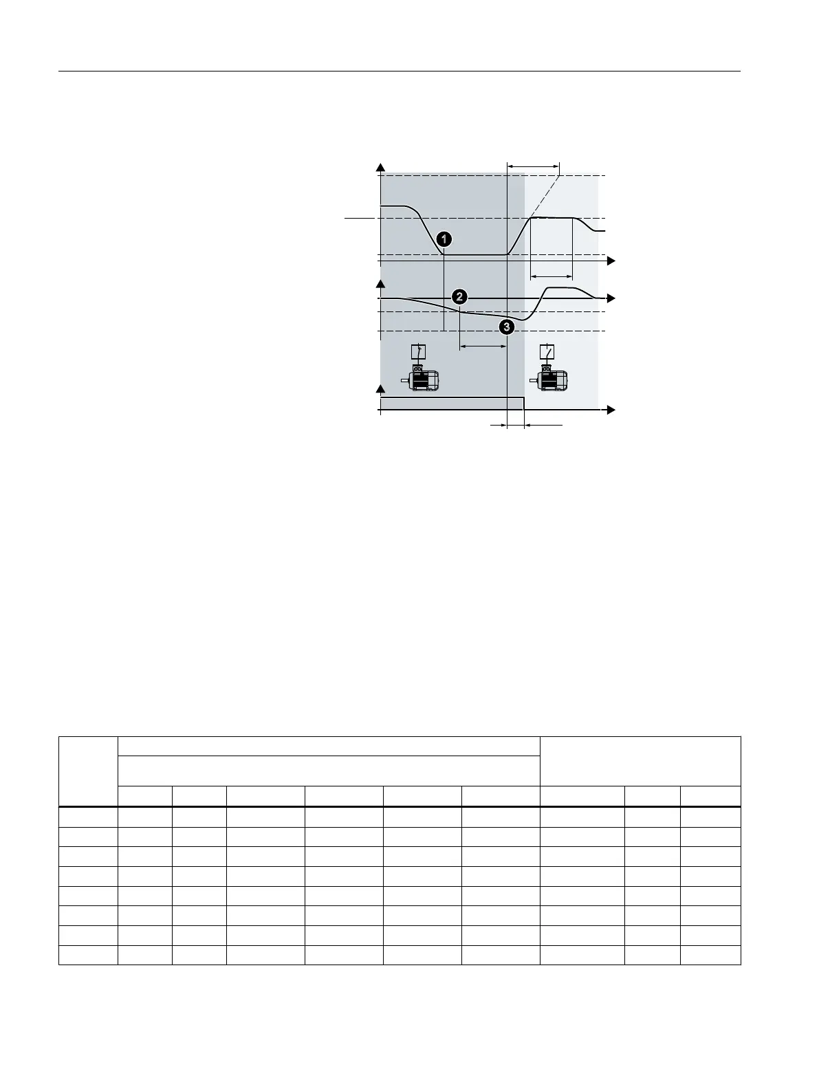
Switching off M1 ... M3 uncontrolled motors
&RQWUROGHYLDWLRQ
0RWRU0QLVFRQQHFWHG
0RWRU'0VSHHG
S
S
S෪
S
S
UQ
UQ
S
W
W
W
S
S
S
S
Figure 6-37 Conditions for switching off a motor
Procedure for switching off an uncontrolled motor:
1. The speed-controlled motor turns with minimum speed p1080.
2. The control deviation of the technology controller is less than -p2373.
3. Time p2375 has expired.
The inverter accelerates the speed-controlled motor with ramp-up time p1120 to the
activation/deactivation speed p2378. Until the activation/deactivation speed p2378 is
attained, the inverter deactivates the technology controller temporarily.
4. After shutdown delay p2386, the inverter disconnects an uncontrolled motor.
Sequence for activating and deactivating the M1 … M3 motors
Table 6-46 p2371 specifies the sequence for activating and deactivating the motors
p2371 → → → Sequence for activating motors → → → Power of the activated M1 … M3
motors compared with the speed-
controlled DM motor
→ → → Sequence for deactivating motors → → →
Stage 1 Stage 2 Stage 3 Stage 4 Stage 5 Stage 6 1 × DM 2 × DM 3 × DM
1 M1 M1 --- ---
2 M1 M1+M2 M1, M2 --- ---
3 M1 M2 M1+M2 M1 M2 ---
4 M1 M1+M2 M1+M2+M3 M1, M2, M3 --- ---
5 M1 M3 M1+M3 M1+M2+M3 M1, M2 M3 ---
6 M1 M2 M1+M2 M2+M3 M1+M2+M3 M1 M2, M3 ---
7 M1 M1+M2 M3 M1+M3 M1+M2+M3 M1, M2 --- M3
8 M1 M2 M3 M1+M3 M2+M3 M1+M2+M3 M1 M2 M3
Advanced commissioning
6.21 Cascade control
Converter with the CU230P-2 Control Units
290 Operating Instructions, 09/2017, FW V4.7 SP9, A5E34257946B AE

 Loading...


